Table of Contents

Summary of Contents for USFilter STRANTROL SYSTEM 5
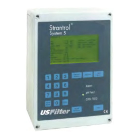
- Page 1 ® STRANTROL SYSTEM5 H, HRR, & T LOWCELL EMPERATURE ENSORS NSTALLATION ROGRAMMING & ANUAL Stranco Products P.O. Box 389 Bradley, IL 60915 866.766.5987 phone 815.932.8154 phone 815.932.1760 fax http://www.stranco.com ©2002 USFilter...
-
Page 3: Table Of Contents
Table of Contents Section Page Introduction ............................ 1 Shipping package contents ......................1 General guidelines........................1 Part I Mounting the System5 Controller ..................3 Step 1: Mounting the controller....................3 Step 2: Wrapping the fittings ....................3 Step 3: Assembling the flowcell ....................3 Step 4: Install the paddlewheel flow switch ................ - Page 4 Table of Contents 14: Modem Callout ...................21 15: Calendar ....................22 16: Access Codes ..................23 Section 2: Representative View Access 1: Main Menu ...................23 2: Recorder Outputs ...................24 3: Diagnostics .....................24 4: Warning Bands ..................26 5: Data Logging ..................27 6: Rep Start-Up ..................27 Part IV: Routine Display .......................30 FCC Compliance..........................30...
-
Page 5: Introduction
Introduction Introduction What’s Included Your shipping package should contain these items: • The Strantrol System5 Controller with Data Modem and Warranty Registration Form • HRR Sensor (Part No. 7042003) • pH Sensor (Part No. 7040002) • Temperature Sensor (Part No. 7047001) •... - Page 6 Page 2...
-
Page 7: Part I Mounting The System5 Controller
“Warning” Failure to incorporate a flow switch and flowcell into the sample stream of your USFilter chemical controller can result in Step 2: Wrapping the Fittings injury or harm to swimmers in or around the pool if the recirculation pump should fail or shut down. -
Page 8: Step 6: Opening The Sample Stream Valve
Part I – Mounting the System5 diagrams). Install the ½-inch ball valves provided to allow isolation of the sample lines. Then remove the cap to the sensor, clean tips and screw it into the flowcell (hand tighten as shown). Give the pH sensor a couple of vigorous shakes before installing. -
Page 9: Part Ii: Wiring The System5
Part II – Wiring the System5 Wiring the System5 Connecting Power to the System5 Step 2: Wiring Directly to the Unit There are two options to connect power to the unit. You may hard wire it to a junction box or wire directly. -
Page 10: Step 4: Setting The Bnc/Pre-Amp Switch
Part II – Wiring the System5 Step 4: Setting the BNC/PRE-AMP Switch Step 6: Running Power to the Unit Notice the switch S6 just above Terminal Block 1 Locate Terminal Block 5 (TB5) in the drawing (TB1) on the Input board in the drawing. This and on your unit. - Page 11 Part II – Wiring the System5 Page 7...
-
Page 12: Step 8: Testing Relays And Priming Pumps
DESTRUCTION. marked TB1-1. The Water Ground forms a connection between TB1-1 and the stainless steel One of the advantages of the USFilter Stranco screw provided in the Flowcell. Products System5 (and all Strantrol Controllers) is that the unit can be used with a flow switch to control the feeder and still not lose power to the sensor. -
Page 13: Step 11A: Connecting A Flow Switch To The Pre-Amp
Part II – Wiring the System5 Step 11a: Connecting a Flow Switch to the Pre- Step 13: Connecting Printer to Modem Board If you are using a printer with the System5, connect the printer (DB-25 male connector) to the modem board as shown in the following chart. - Page 14 Part II – Wiring the System5 Page 10...
-
Page 15: Part Iii: Programming The System5
Section 1: Manager and Operator View Access 1. Main Menu * If you have requested your USFilter Stranco Products representative to include Cal. LSI SETUP, Ryznar Stability Index (read only value), Once you have selected the access level the screen... -
Page 16: 3: Programming Ph Setup
Part III – Programming the System5 3. Programming pH Setup If you choose pH Setup from the Main Menu, the Screen will display some or all of the following choices (depending upon your system needs). Next to all of the choices but pH Calibrate is the current programmed value for that option. -
Page 17: 4: Programming Hrr Setup
Part III – Programming the System5 4: Programming HRR Setup Next to all of the choices but HRR Calibrate is If you choose HRR Setup from the Main Menu, the Screen will display some or all of the the current programmed value for that option. following choices (depending upon your system Type in the number of the option you would like needs). -
Page 18: 5: Programming Ppm Setup
Part III – Programming the System5 5: Programming PPM Setup Next to all of the choices but ppm Calibrate is the If you choose PPM Setup from the Main Menu, the Screen will display some or all of the current programmed value for that option. Type following choices (depending upon your system in the number of the option you would like to needs). -
Page 19: 6: Programming Temp Setup
Part III – Programming the System5 6: Programming Temp Setup Next to all of the choices but Temperature If you choose Temp Setup from the Main Menu, the Screen will display some or all of the Calibrate is the current programmed value for following choices (depending upon your system that option. -
Page 20: 8: Programming Sensor Wash
Part III – Programming the System5 7a: Entering New Values for Calculate LSI Setup Type in the number of the variable you would Selecting 0 (Enter LSI parameters) displays the following screen and prompt you to enter the like to enter. The screen will display the previous new value. -
Page 21: 9: Programming Alternate Hrr Setpoint
Part III – Programming the System5 9: Programming Alternate HRR Setpoint If you would like to use a different setpoint for Next to each choice is the current programmed certain times of the day to compensate for value for that option. Type in the number of the option you would like to program. -
Page 22: 10: Programming Dechlorination
Part III – Programming the System5 10: Programming Dechlorination Next to each choice is the current programmed value for that option. Type in the number of the would like employ rapid dechlorination process (such after option you would like to program. The screen Superchlorination), Choose Dechlorination from will display the previous value selected and the Main Menu. -
Page 23: 11: Programming Superchlorination
Part III – Programming the System5 11: Programming Superchlorination Next to each choice is the current programmed If you would like to use Superchlorination to eliminate chloramines, choose Superchlorination value for that option. Type in the number of the from the Main Menu. The screen will display option you would like to program. -
Page 24: 12: Relay Modes
Part III – Programming the System5 12: Relay Modes Next to each choice is the current programmed If you choose Relay Modes from the Main Menu, the Screen will display some or all of the value for that option. Type in the number of the following choices (depending upon your system option you would like to program and then Press needs). -
Page 25: 13: Communication
Part III – Programming the System5 13: Communication Next to each choice is the current programmed value for that option. Type in the number of the If you choose Communication from the Main Menu, the Screen will display some or all of the option you would like to program. -
Page 26: 15: Calendar
Part III – Programming the System5 14a: Entering New Values for Modem Callout For each option you select from the Modem Callout Menu the screen will display the previous value selected for that option and prompt you to enter the new value. The following table will help you decide what values to enter. -
Page 27: 16: Access Codes
Part III – Programming the System5 16: Access Codes If you choose Access Codes from the More Selecting Manager Codes will allow you to Choices option on the Main Menu, the Screen program codes for up to six operators. Selecting will display some or all of the following choices Enable Option for Operator Level will allow you (depending upon your system needs). -
Page 28: 2: Recorder Outputs
Part III – Programming the System5 2: Recorder Outputs Choosing Version displays the version of the Selecting Recorder Outputs from the Main software you are using and displays “Factory Defaults”. Selecting Factory Defaults at this Menu will display the following choices for programming. - Page 29 Part III – Programming the System5 3b: Hardware Calibration 3b-1: Entering New Values for Hardware Calibration If you choose Hardware Calibration from the Diagnostics Menu, the screen will display some For each option you select from the Hardware or all of the following choices (depending upon Calibration Menu the screen will display the your system needs).
-
Page 30: 4: Warning Bands
Part III – Programming the System5 4: Warning Bands Next to each choice is the current programmed If you choose Warning Bands from the Main value for that option. Type in the number of the Menu, the screen will display some or all of the following choices (depending upon your system option you would like to program. -
Page 31: 5: Data Logging
Part III – Programming the System5 5: Data Logging Next to each choice is the current programmed If you choose Data Logging from the Main Menu, the screen will display some or all of the value for that option. Type in the number of the following choices (depending upon your system option you would like to program. - Page 32 Part III – Programming the System5 6a: Entering New Values for Rep Start Up For each option you select from the Rep Start Up Menu the screen will display the previous value selected for that option and prompt you to enter the new value. The following table will help you decide what values to enter.
-
Page 33: Part Iv: Routine Display
Part IV – Routine Display Routine Display Pressing the Setpoint Key at any time will display The System5 routine display screen shows the the current setpoints. Customer Name, Location, and Rep phone number on the facepanel as well as a special box Pressing the Mode Key at any time will display (the alarm scroll) for alarm messages and current the current feed modes for each pump. - Page 36 Unit A1, 6-8 Lyon Park Road Priory Works, Tonbridge P.O. Box 389 North Ryde, NSW 2113 Kent, TN11 0QL Bradley, IL 60915 U.S.A. Australia United Kingdom 866.766.5987 phone +61.(2).8875.2800 phone 011.44.1732.354888 phone 815.932.8154 phone +61.(2).8875.2700 fax 011.44.1732.354222 fax 815.932.1760 fax http://www.stranco.com © 2002 USFilter ST-SYS5-MAN-Rev0102...
Need help?
Do you have a question about the STRANTROL SYSTEM 5 and is the answer not in the manual?
Questions and answers