Table of Contents
Advertisement
Advertisement
Table of Contents

Summary of Contents for SINO SDS6
- Page 1 SINO DIGITAL READOUTS SDS6 Operation Manual GUANGZHOU LOK SHUN CNC EQUIPMENT LTD.
- Page 2 It is recommended that: ● Instructions for panel keys of the SDS6 digital display meter that is applicable to this manual are listed in P1~4 of the above Section 1. ● Read through follow safety precautions and Section 2( see P102~107), which are very important to the safe operation of your digital display meter.
- Page 3 Notes: ● Disconnect power plug promptly if the digital display meter emits smog or peculiar smells, when an electric shock or fire may be caused when continuing to use it. Please contact Guangzhou Lokshun CNC Equipment Ltd. or dealer and never attempt to repair it by yourself. ●...
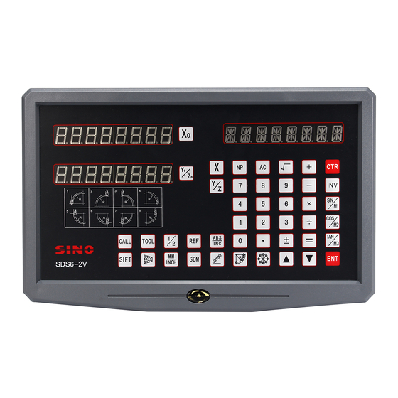
- Page 4 Illustration of Panel and Keyboard SDS6-3V READOUT PANEL AND KEYBOARD SDS6-2V READOUT PANEL AND KEYBOARD...
- Page 5 Illustration of Panel and Keyboard Caption of the Keyboard of SDS6 Keys for cleaning the displayed value to zero Keys for Axis selection Entry keys for digits ÷ × Operation Key (in Calculation function key) Calculation function key (in Calculation function key)
- Page 6 Illustration of Panel and Keyboard Key for entering data Key for cleaning the displayed value to zero Function key for getting one half Key for the conversion the meter System/ British system display Function key for Sleep Function key for 200 zero Position R angular ARC function key (ARC Function key)
- Page 7 Key for taper measure function Key for calling 200 tool storeroom TOOL Key for input 200 tool storeroom Key for radius Function key for machine output (EDM) (only SDS6-3V readout has) Function key for data filtration (only SDS6-2V readout has)...
- Page 8 Catalogue Catalogue A. Basic Functions …………………………………………………………. 1 B. Smooth R ……………………………………………………………….. 15 (Be the same with: MIIL_MS 、MIIL_M) C. Simple R ………………………………………………………………... 27 (Be the same with: 2V-MIIL_MS 、2V-MIIL_M) D. Hole Drilling Along An Oblique Line ………………………………… 34 (Be the same with: MIIL_MS) .
- Page 9 Catalogue I. Tool Diameter Compensation ………………………………………… 74 (Be the same with: 3V-MIIL_MS) J. 200 Tool Storeroom……………………………………………………. 77 (Be the same with: LATHE) K. The Function Of Measure For Taper ……………………………….. 81 (Be the same with: LATHE) L. (EDM)Matching Output Function ………………………………….. 83 (Be the same with: 3V-EDM) M.
- Page 10 A. Basic Function Basic Functions...
- Page 11 A. Basic Function We take pleasure to tell you that this machine tool optical digital display ruler device you are using is the one most popular in Europe. You will be able to use this device easily after you have read this manual thoroughly.
- Page 12 , next step 6) Setting count direction of axis Z linear encoder. Setting method alike axis X. , next step 7) choose machine type SDS6-3V readout: multifunctional milling machine readout universal milling machine readout discharging processing readout lathe machine readout SDS6-2V readout:...
- Page 13 A. Basic Function value displays in Y-axis LED. ,next step Press Note: only 3 axis lathe machine has this function. 9) choose compensation type choose line error compensation “LINEAR”; choose Segmented error compensation “SEGMENT”; ,next step Press 10)choosing the display type of the axis linear display function“RAS_X”...
- Page 14 A. Basic Function 4. Presetting data 1) As shown in the figure, after the processing of Hole A finished, the position of the working piece has been adjusted, Hole B is to be processed. 2) Align the Tool with Hole A. 3) Select the key for axis, key 4) Key ,Enter the value(If the entered value...
- Page 15 A. Basic Function 4) Key 5) Move the machine tool to Position C. 6) Move the machine tool to Position D. 7) Return to the absolute mode 8) Move the machine tool to Position E. Note: The resetting in the absolute and the relative display mode must be done separately.
- Page 16 A. Basic Function key display As shown in the figure, the enter between two points is to be found. 1) Let the tool touch the one edges of the working piece and Return the X-axis displayed Value to zero, then move the tool along the direction of arrow and let it come to touch the other edges of the working piece, then do the next step can determine the center position.
- Page 17 A. Basic Function In the function of Y, Z axis summing, press can switch the display mode. 1) if the former display mode is summing, press switch to separate mode. 2) if the former display mode is separation, press switch to summing mode. Note: only the lathe machine digital displayer has the function;...
- Page 18 A. Basic Function origin. (Figure 1) 2. To carry out error compensation taking the 1 absolute zero of the raster ruler as the mechanical origin. (Figure 2) L: The distance of effective range of raster ruler L1: Length of the compensation segment L2: Effective distance of the compensation segment Set up according to the sketch map 1.
- Page 19 A. Basic Function error.) 4)Find the mechanical origin There are two methods for setting the compensation origin. 1、directly press to choose the current position as origin. 2、Press to choose the 1st absolute zero of the raster ruler as the mechanical origin. Move towards the positive direction of X axis of the machine tool and search for the 1st absolute zero of the raster ruler as the mechanical origin.
- Page 20 A. Basic Function Input the compensation setup of the 3rd segment Press Press , and enter into the next set-up point Input the compensation setup of the 4th segment Press Press , and enter into the next set-up point Input the compensation setup of the 5th segment Press Press , and enter into the next set-up point...
- Page 21 A. Basic Function Finding the function of the mechanical origin If there is power off when the raster ruler is moving, or the rater ruler is moved before the power is on, after re-start, the mechanical origin needs to be found again.
- Page 22 A. Basic Function L'---the displayed value on digital display meter (mm) S---the actually factor (mm/m), "+" symbol means the actual length is larger, and "-" symbol means the actual length is smaller. Compensation range: -1.500 mm/m~+1.500 mm/m Example: The Actual metered length of the machine tool machine table is 1000 mm, and the display value on the digital display meter is 999.98 mm.
- Page 23 A. Basic Function new situation. If the operator want to suspend the processing for his (her) rest time or any time he (she) is occupied by other thing, the sleep switch can be used to avoid the above mentioned situation. In not ALE working state, if there a need of Sleep Switch Off, key ,the digital display box will turn off the display.
- Page 24 B. Smooth R(Be the same with: MIIL_MS 、MIIL_M) Smooth R (Be the same with: MIIL_MS 、MIIL_M)
- Page 25 The advanced smooth R arc Calculation function provided in SDS6 model digital display box makes it possible to complete the processing of a single piece such as moulding copper electrode easily and quickly with a universal milling machine.
- Page 26 B. Smooth R(Be the same with: MIIL_MS 、MIIL_M) 2) Let us recognize the plane coordinate and the start and end angles of a circular arc. In Plane XY、XZ or YZ, the coordinate of a point is its position with respect to the zero point on the plane.
- Page 27 B. Smooth R(Be the same with: MIIL_MS 、MIIL_M) 3) The procedure in using the Arc R Calculation function. As shown in the figures(a)、(b)and (c), reset all the axes after finishing the installation of Tool and the related tool setting (assign the position of the tool after tool setting as the zero point).
- Page 28 B. Smooth R(Be the same with: MIIL_MS 、MIIL_M) 7. Enter the start angle of the circular arc (ST ANG) This determines the position of the first cut feed in the processing of circular arc. As show in Fig.(b), the start angle is 0° if the arc is to be processed from Point E to Point F, and 90°...
- Page 29 B. Smooth R(Be the same with: MIIL_MS 、MIIL_M) If finish the tool setting as shown in Fig. (b). ± ± φ5 φ5 6) Enter the radius of the circle. 7) Enter the diameter of the tool. 8) Enter the maximal cut. 9) Enter the start angle of the arc.
- Page 30 B. Smooth R(Be the same with: MIIL_MS 、MIIL_M) 11) Determine inner/outer circle mode. 12) It is display that the processing start at the first point. Tool setting as Fig. (a) Tool setting as Fig. (b) 13) Move the machine tool to bring the display value on X- and Y-axes into zero, reach the start point of R.
- Page 31 B. Smooth R(Be the same with: MIIL_MS 、MIIL_M) 4) Select Plane XZ. 5) Enter the position of the circle center. If you use a circular arc milling tool, finish tool setting as shown in Fig. (a). ± If you use a circular arc milling tool, finish tool setting as shown in Fig.
- Page 32 B. Smooth R(Be the same with: MIIL_MS 、MIIL_M) 7) Enter the diameter of the tool. Use a circular arc milling tool Use a flat end milling tool 8) Enter the maximal cut. 9) Enter the start angle of the arc. 10) Enter the end angle of the arc.
- Page 33 B. Smooth R(Be the same with: MIIL_MS 、MIIL_M) Use a flat end milling tool setting as Fig. (a) Use a flat end milling tool setting as Fig. (b) 13) Move the machine tool to bring the display value on X- and Y-axes into zero, reach the start point of R.
- Page 34 B. Smooth R(Be the same with: MIIL_MS 、MIIL_M) φ 5 2. At first, finish tool setting and return the boring ring scales on X- and Z- axes to zero. 1) Key , enter ARC function. 2)choose smooth function press press (only 2V readout has this set item,3V readout has only smooth R function, so hasn’t this set item and directly get into next step)...
- Page 35 B. Smooth R(Be the same with: MIIL_MS 、MIIL_M) 9) Enter the start angle of the arc. 10) Enter the end angle of the arc. 11) Determine inner/outer circle mode. 12) It is display that the processing start at the first point. 13) enter the processing and display the first point.
- Page 36 C. Simple R(Be the same with: 2V-MIIL_MS、2V-MIIL_M) Simple R (Be the same with: 2V-MIIL_MS、2V-MIIL_M)
- Page 37 C. Simple R(Be the same with: 2V-MIIL_MS、2V-MIIL_M) Simple Arc R Calculation function: One who is not quite at home in the concepts of plane coordinates will feel difficult in using smooth arc function. If the arc to be processed is simple enough, and the required smoothness is average, the simple arc R function may be a good choice.
- Page 38 C. Simple R(Be the same with: 2V-MIIL_MS、2V-MIIL_M) 、 3. Select the processing plane, XY XZ or YZ. (ARC-XY) (ARC-XZ) (ARC-YZ) 4. Enter the of the circular arc (RDDIUS) 5. Enter the diameter of the tool (TL DLA): When processing the arc in Planes XZ and YZ, end mill is used and the processing in carried by the end edge of the tool, so the diameter valve to be entered should be zero.(refer to step 5 in the operation procedure of the smooth R function).
- Page 39 C. Simple R(Be the same with: 2V-MIIL_MS、2V-MIIL_M) L= R L= R+ the radius of the tool L= R+ the radius of the tool L= R L= R+ the radius of the tool L= R+ the radius of the tool L1= R L1= R L2= the radius of the tool L2= the radius of...
- Page 40 C. Simple R(Be the same with: 2V-MIIL_MS、2V-MIIL_M) 3) Select the processing plane 4) Select Plane XZ 5) Enter the radius of the circular arc 6) Enter the radius of the tool 7) Enter the maximal cut 8) Start processing Point A as the start point(0,0) Point B as the start point(0,0) 9) Refer to the display, move the machine tool to bring the displayed value on X axis into zero, then turn the Z axis star wheel to let the machine table rise or...
- Page 41 C. Simple R(Be the same with: 2V-MIIL_MS、2V-MIIL_M) *Take the processing of an inner circular arc as example: 1) At first, align the tool to face just the start point(Point A or Point B), to enter ARC function. Select the simple function, key 2) Select the way of the R processing Point A is the start point, key Point A is the start point, key...
- Page 42 C. Simple R(Be the same with: 2V-MIIL_MS、2V-MIIL_M) 9) Refer to the display, move the machine tool to bring the displayed valve on X axis into zero, then turn the Z axis star wheel to let the machine table rise or drop by the displayed value in Y axis.
- Page 43 D. Hole Drilling Along An Oblique Line(Be the same with: MIIL_MS) Hole Drilling Along An Oblique Line (Be the same with: MIIL_MS)
- Page 44 D. Hole Drilling Along An Oblique Line(Be the same with: MIIL_MS) The function of hole drilling along an oblique line Normally, for processing the working pieces shown in the right figure the operator must calculate out the distance between two neighboring holes in X- and Y- axes;...
- Page 45 D. Hole Drilling Along An Oblique Line(Be the same with: MIIL_MS) 4) Enter the length of the oblique line 5) Enter the angle 6) Enter the number of holes 7) The position of the first hole is displayed, enter processing state. 8) Key to display the position of next processing point, and then move the machine tool to bring the displayed value on both X- and Y-axes into zero.
- Page 46 D. Hole Drilling Along An Oblique Line(Be the same with: MIIL_MS) 4) Enter the step length 5) Enter the angle 6) Enter the number of holes 7) Enter processing state 8) Key to display the position of next processing point, and then move the machine tool to bring the displayed value on both X- and Y-axes into zero.
- Page 47 . The Function For 200 Point(Be the same with: MIIL_MS、MIIL_M、EDM) The Function For 200 Point Subsidiary Zero Positions (Be the same with: MIIL_MS、MIIL_M、EDM)
- Page 48 . The Function For 200 Point(Be the same with: MIIL_MS、MIIL_M、EDM) 200 subsidiary zero position function: 200 auxiliary zero position function: also is called 200 user Coordinate System (UCS) function. ALE: Absolute Coordinate System. ALE is the “reference” system. All 200 UCS are defined relative to the ALE. ALE is confirmed in the initialization of the work piece process, which doesn’t change if the work piece no changed.
- Page 49 . The Function For 200 Point(Be the same with: MIIL_MS、MIIL_M、EDM) every UCS taking a subsidiary zero position as its original points to perform the processing when need. 2. In the display mode of every UCS, processing with various special function can be performed.
- Page 50 . The Function For 200 Point(Be the same with: MIIL_MS、MIIL_M、EDM) 1) After setting the zero position in the absolute mode, the system automatically perform a keeping in memory operation, in order that once a power interruption happen in the course the zero position may be tracked back. 2) Enter the UCS display mode.
- Page 51 . The Function For 200 Point(Be the same with: MIIL_MS、MIIL_M、EDM) 7) Enter the display mode of the third zero position. The setting of all the subsidiary zero positions of the working piece shown in Fig. (1) has been finished. Why the enter position coordinates of every subsidiary zero position are just in the opposite direction of the displayed values? Let us explain this with the above example.
- Page 52 . The Function For 200 Point(Be the same with: MIIL_MS、MIIL_M、EDM) 3) Enter the display node of the first UCS. 4) Set the subsidiary zero position. 5) Return to the absolute state display mode 6) Move the machine table of the machine tool to Point 2.
- Page 53 . The Function For 200 Point(Be the same with: MIIL_MS、MIIL_M、EDM) 12) Clear, ser the third subsidiary zero point. 13) Return to the absolute state display mode. Continue to touch four time key The setting of all the subsidiary zero positions of the working piece shown in Fig. (1) has been finished.
- Page 54 . The Function For 200 Point(Be the same with: MIIL_MS、MIIL_M、EDM) 4) Process Hole A. 5) Enter the display mode of the second UCS. 6) Move the working of the machine tool to Point B X axis display -15, Y axis display 0. 7) Process Hole B 8) Move the machine tool to Point C.
- Page 55 . The Function For 200 Point(Be the same with: MIIL_MS、MIIL_M、EDM) For PCD function, please refer to the related sections. Ⅴ. The Clearing of Subsidiary Zero Positions and Other Related Problems. 1. The Clearing of Subsidiary zero positions In absolute state (ALE state), key 10 times continuously, the memory about all the subsidiary zero positions will be cleared, the 200 subsidiary zero positions will become the same point of the zero position in the absolute state.
- Page 56 . The Function For 200 Point(Be the same with: LATHE) The Function For 200 Point Subsidiary Zero Positions (Be the same with: LATHE)
- Page 57 . The Function For 200 Point(Be the same with: LATHE) 200 subsidiary zero position function: 200 auxiliary zero position function: also is called 200 user Coordinate System(UCS) function. ALE: Absolute Coordinate System. ALE is the “reference” system. All 200 UCS are defined relative to the ALE. ALE is confirmed in the initialization of the work piece process, which doesn’t change if the work piece no changed.
- Page 58 . The Function For 200 Point(Be the same with: LATHE) example, Points 1、 2 and 3 in Fig. (1). It is possible to enter the display mode of every UCS taking a subsidiary zero position as its original points to perform the processing when need.
- Page 59 . The Function For 200 Point(Be the same with: LATHE) 2) Enter the UCS display mode. (Two Method) Method 1: Method 2: 3) Enter the position of the first subsidiary zero position. ± 4) Enter the position of the second UCS. 5) Enter the position of the second zero position.
- Page 60 . The Function For 200 Point(Be the same with: LATHE) Why the direction of each coordinate of your input auxiliary zero position opposite to that of the display result? As the above example illustrates, under the user coordinate display mode, if your enter the coordinate of auxiliary zero position on the position of the zero position under absolute state, the display result will be the position of absolute state zero position in this user coordinate.
- Page 61 . The Function For 200 Point(Be the same with: LATHE) A(0,0) Fig.(2) The work piece has been roughly turned, and has to be semi subtly turned. The unilateral allowance through rough turning is 0.05, the subtle turning will the surface of the work piece to meet the roughness requirements. First set the absolute coordinate origin at Point A, then directly the position of the auxiliary zero point according to the setting method I for auxiliary zero point to set up the user coordinate system.
- Page 62 . The Function For 200 Point(Be the same with: LATHE) 5) Process the encircle Φ40 start cutting until the displays on X axis and Y turn out 0. 6) Enter the third user coordinate system. 7) Process the encircle Φ60 Start cutting until the displays on X axis and Y turn out 0.
- Page 63 . The Function For 200 Point(Be the same with: LATHE) 2. Reset during a subsidiary zero position is being used A subsidiary zero position is being used of course under the display mode of the corresponding UCS, resetting in this state is actually to reset a new subsidiary zero position.
- Page 64 . The Function For 200 Point(Be the same with: 2V-GRIND) The Function For 200 Point Subsidiary Zero Positions (Be the same with: 2V-GRIND)
- Page 65 . The Function For 200 Point(Be the same with: 2V-GRIND) 200 subsidiary zero position function: 200 auxiliary zero position function: also is called 200 user Coordinate System (UCS) function. ALE: Absolute Coordinate System. ALE is the “reference” system. All 200 UCS are defined relative to the ALE. ALE is confirmed in the initialization of the work piece process, which doesn’t change if the work piece no changed.
- Page 66 . The Function For 200 Point(Be the same with: 2V-GRIND) every UCS taking a subsidiary zero position as its original points to perform the processing when need. 2. In the display mode of every UCS, processing with various special function can be performed.
- Page 67 . The Function For 200 Point(Be the same with: 2V-GRIND) 1) After setting the zero position in the absolute mode, the system automatically perform a keeping in memory operation, in order that once a power interruption happen in the course the zero position may be tracked back. 2) Enter the UCS display mode.
- Page 68 . The Function For 200 Point(Be the same with: 2V-GRIND) The setting of all the subsidiary zero positions of the working piece shown in Fig. (1) has been finished. Why the direction of each coordinate of your input auxiliary zero-position opposite to that of the display result? As the above example illustrates, under the user coordinate display mode, if your enter the coordinate of auxiliary zero position on the position of the zero position under absolute state, the display result will be the position of absolute state...
- Page 69 . The Function For 200 Point(Be the same with: 2V-GRIND) 2) Enter the number. 3) Process the plane A, E Start grinding until the displays on both X axis and Y turn out 0. 4) Enter the second user coordinate system. 5) Process the plane B, C Start grinding until the displays on both X axis and Y turn out 0.
- Page 70 . The Function For 200 Point(Be the same with: 2V-GRIND) 2. Reset during a subsidiary zero position is being used A subsidiary zero position is being used of course under the display mode of the corresponding UCS, resetting in this state is actually to reset a new subsidiary zero position.
- Page 71 F. PCD Circle Equally Dividing Holes(Be the same with: MIIL_MS、MIIL_M、EDM) PCD Circle Equally Dividing Holes (Be the same with: MIIL_MS、MIIL_M、EDM)
- Page 72 F. PCD Circle Equally Dividing Holes(Be the same with: MIIL_MS、MIIL_M、EDM) Circular arc equally Dividing Function(PCD Function) This function may be used to divide a circular arc equally, for example in the processing of drilling holes distributed uniformly on a flange. After selecting this function, the message window will prompt for various parameters to be defined for the operator.
- Page 73 F. PCD Circle Equally Dividing Holes(Be the same with: MIIL_MS、MIIL_M、EDM) 2) Key select processing plane. Enter the parameter Select Plane XY. , next step. (only 3V readout has this set item, 2V readout has only XY plane, so hasn’t the item and can directly get into next step) 3) Enter the center position of the circular arc.
- Page 74 F. PCD Circle Equally Dividing Holes(Be the same with: MIIL_MS、MIIL_M、EDM) 6) Enter the start angle. , next step. 7) Enter the end angle. If the arc is dividing by 6 points. , next step. If the whole circle is divided by 7 point. , next step.
- Page 75 G. Angular Surface Processing(Be the same with: MIIL_MS) G. Angular Surface Processing ( Be the same with: MIIL_MS)
- Page 76 G. Angular Surface Processing(Be the same with: MIIL_MS) Angular Surface Processing When the processing of a rather large angular surface is one part of job, the angular processing function can make the job much easier. Ⅰ. Aligning for the bank angle: When the processing surface is Plane XY as in the case of the fitting shown in Fig.
- Page 77 G. Angular Surface Processing(Be the same with: MIIL_MS) 2) Select Plane XY. 3) Enter the angle of the angle surface 4) Move the machine table along X axis. Let the metering tool come just in contact with the working piece, and adjust the scale reading into zero, then move the machine table an arbitrary distance along X axis.
- Page 78 G. Angular Surface Processing(Be the same with: MIIL_MS) 1. Select Plane XZ or YZ. 2. Enter the diameter of the tool (DIA). 3. Enter the start point (ST POS). 4. Enter the end point (ED POS). 5. You may quit the angular surface processing function at will, just key Refer to the example: 1)Align for the bank angle, finish tool setting, and key...
- Page 79 G. Angular Surface Processing(Be the same with: MIIL_MS) and respectively the position of last/next processing point will be displayed. You may quit the angular processing function at will, just key...
- Page 80 H. The Function Calculator Function(Be the same with: MIIL_MS) The Function Calculator Function (Be the same with: MIIL_MS)
- Page 81 The Calculation function Some time it is necessary to calculate out some values during the processing, SDS6 Series digital display boxes are provided with simple Calculation function. The details are as following: All the resulted value is displayed on X axis.
- Page 82 H. The Function Calculator Function(Be the same with: MIIL_MS) Make the following calculation: √ =31.623 The distance AB in the figure = × × — 31.623 √ 90° Display for the result: Transfer the value 31.62277 to Y axis. As shown in the figure, the distance AB=31.62277, the tool is at Point A, move the machine table to bring the displayed value into zero, the position of Point B is reached, the processing of Hole B may start.
- Page 83 I. Tool Diameter Compensation(Be the same with: 3V-MIIL_MS) Tool Diameter Compensation ( Be the same with: 3V-MIIL_MS)
- Page 84 I. Tool Diameter Compensation(Be the same with: 3V-MIIL_MS) The Tool Diameter Compensation Function In the processing of the four sides of the fitting shown in (1), the operator has to run for an additional feeding distance equal the diameter of the tool in every side to complete the processing of the whole length, φ6 if the tool diameter compensation function is...
- Page 85 I. Tool Diameter Compensation(Be the same with: 3V-MIIL_MS) 2) Select a processing mode preset. Start the processing at the position shown in Fig. (2) Start the processing at the position shown in Fig. (3) 3) Enter the diameter of the tool 4) Enter processing state ①...
- Page 86 J. 200 Tool Storeroom(Be the same with: LATHE) 200 Tool Storeroom (Be the same with: LATHE)
- Page 87 It will need to use different tools when turning different work pieces or different surface of work pieces, so it is necessary to uninstall and adjust the tools, SDS6 digital readout has the function of 200 tools storeroom, which makes the operation simple.
- Page 88 J. 200 Tool Storeroom(Be the same with: LATHE) Notes: the Y-axis value mentioned above is the integrated value of Y-axis with Z-axis, namely the Z/Z0-axis in the former lathe machine readout. The operation of inputting the datum of tools and calling tool: 1) Please input the datum of tools, in the “ALE”...
- Page 89 J. 200 Tool Storeroom(Be the same with: LATHE) Default the first tool as the base tool, you can also set the other tool as the base tool, key number is OK. Key can call other tools. 3) Call the second tool. 4) Exit Move the flat-from to make the display value of X axis and Z/Z axis become...
- Page 90 K. The Function Of Measure For Taper(Be the same with: LATHE) The Function Of Measure For Taper (Be the same with: LATHE)
- Page 91 K. The Function Of Measure For Taper(Be the same with: LATHE) The Function of measure for taper: The taper of work piece can be measured when turning the taper work piece. Operation: As figure shows, the nod of lever meter is touched the position A of work piece surface.
- Page 92 L. (EDM) Matching Output Function(Be the same with: 3V-EDM) (EDM) Matching Output Function (Be the same with: 3V-EDM)
- Page 93 “negative”, namely, the “negative processing” as shown is Fig. Model SDS6-3V digital display case also possesses the “negative anti fire height” function that other cases of similar kinds cannot offer. This function is delivered by a kind of intellectual location tracing, testing and protecting device.
- Page 94 L. (EDM) Matching Output Function(Be the same with: 3V-EDM) intellectual location tracing, testing and protecting device. In the positive processing, electrode the electrode surface will be covered by workpiece accumulative carbon; in case of long time processing and overtime processing not under control by anybody, such accumulated carbon is not cleaned by anyone;...
- Page 95 L. (EDM) Matching Output Function(Be the same with: 3V-EDM) 4) X-axis will display “target value of personal location” Y-axis will display “value of depth reached”. Note: Values on Y-axis means the depths reached on the work piece by processing. Z-axis will display “real time value of personal location”. Note: Values on Z-axis mean the values of locations of main axis electrode on Z-axis.
- Page 96 L. (EDM) Matching Output Function(Be the same with: 3V-EDM) 3) Set “negative anti-fire height: Enter a height, i. e. “150”. 4) Enter the “Exit Mode” Setup. Set at “pause mode”. “AUTO” means automatic mode, “STOP” refers to pause mode. If the original exit mode is pause mode, and “STOP”...
- Page 97 L. (EDM) Matching Output Function(Be the same with: 3V-EDM) Press to choose mode 1. the relay act as list below: A power off, relay OFF B CPU resetting, relay OFF C CPU start-up, relay OFF D Running function EDM , relay OFF E Reach the depth of function EDM setting, relay ON You shall first make sure the mode is positive processing: in negative processing, for the work piece as shown in Fig.
- Page 98 L. (EDM) Matching Output Function(Be the same with: 3V-EDM) electrode work piece 2) Put in depth of processing. 3) Enter the depth value. 4) Start processing. 5) “EDM E” display lasts for 3 seconds long. Return to the state before processing. Example 2: Work piece shown in the processing drawing (c).
- Page 99 L. (EDM) Matching Output Function(Be the same with: 3V-EDM) electrode work piece 2) Enter “EDM” 3) Enter the depth value. ± 4) Start processing 5) Reach the target value. “EDM E” display lasts for 3 seconds and then exits automatically. 5.
- Page 100 L. (EDM) Matching Output Function(Be the same with: 3V-EDM) 2) Put in depth of processing. 3) Enter the depth value. ± 4) Start processing 5) Reach the target value. “EDM E” display lasts for 3 seconds and then exits automatically. 6.
- Page 101 L. (EDM) Matching Output Function(Be the same with: 3V-EDM) 8. back panel EQUAL OUT port EQUAL OUT port is connected to the output of relay, 1.0A30DC 0.5A125VAC 0.3A60VDC SIGNAL COLOR OF WIRE NC(Normal Close) Brown COM(Common) Blue NO(Normal Open) Yellow-green...
- Page 102 M. Digital Filter Function(Be the same with: 2V-GRIND) Digital Filter Function ( Be the same with: 2V-GRIND )
- Page 103 Digital filter function: In grinding process, the readout display value will change quickly because of the vibration of the grinding machine, it will made operator indisposed. SDS6-2V special readout for grinding machine has the digital filter function, it delays the readout display value when the grinding machine is vibrating.
- Page 104 N. N3 Function (Be the same with: 2V-MIIL_MS) N3 Function (Be the same with: 2V-MIIL_MS)
- Page 105 N. N3 Function (Be the same with: 2V-MIIL_MS) the function is suit for Z axis vertical slope machining. There are four machining mode, as following example: ① ΔZ=0.1 A=60˚ ② ΔZ=0.1 A=120˚ ③ ΔZ=-0.1 A=-120˚ ④ ΔZ=-0.1 A=-60˚...
- Page 106 N. N3 Function (Be the same with: 2V-MIIL_MS) Operation steps was show as fallow: (Take the processing plane XZ as an example) 1) Move the tool to the start point, (plane YZ). ,enter N3 function. 2) Key ,select the processing 3) Key plane.
- Page 107 N. N3 Function (Be the same with: 2V-MIIL_MS) 8) Point 2, move axis X to 0, move axis Z 0.1mm forward. ,next point. 9) Point 3, move axis X to 0, move axis Z 0.1mm forward. ,next point. The last point 10) The last point, move axis X to 0, move axis Z 0.1mm forward.
- Page 108 O. The Progressive Progressing(Be the same with: 2V-MIIL_MS) The Progressive Progressing of rectangular Inner chamber (Be the same with: 2V-MIIL_MS)
- Page 109 O. The Progressive Progressing(Be the same with: 2V-MIIL_MS) The progressive progressing of rectangular inner chamber When the job is to process the inner chamber of the fitting shown by the working drawing of Fig. (1), the progressive inner chamber processing function may be used;...
- Page 110 O. The Progressive Progressing(Be the same with: 2V-MIIL_MS) 5) Enter processing state. 6) Move the machine table to bring the displayed values on both X- and Y-axes into zero. 7) Key to display the processing position of next step, refer to the prompts and move the machine to bring the displayed values on both X- and Y- axes into zero.
- Page 111 Additional sheet Additional sheet: Ⅰ. What the user must know: 1. The digital display box must be handle carefully. 2. The box must be grounded properly. 3. Power voltage selection: AC 80V~260V 50 Hz~60 Hz 4. Power consumption: 25VA 5. Working temperature: 0℃~45℃ 6.
- Page 112 Additional sheet Ⅱ. Trouble shooting and handling: Troubleshooting of Grating Ruler and Digital display Meter The following troubleshooting is primary only. If there are still problems, do not dismantle them by yourself, seek help from our company or corresponding agents. Symptom of Source of failure Troubleshooting...
- Page 113 Additional sheet Symptom of Source of failure Troubleshooting failure Grating 1. Grating ruler falls outside the 1. Repair the grating ruler. ruler does usable range of length, not count reading head cracked up. 2. Reading head of grating ruler 2. Repair the grating ruler. rubs ruler enclosure, and aluminum chips piled up.
- Page 114 Additional sheet Ⅲ. Structural principle Our linear encoder and digital readout are high technologic production that is combined with photo electronic technology, precision mechanical technology, microelectronic technology computer technology, and so on. The customer without being trained may not repair this system.
- Page 115 Additional sheet Ⅴ. product packaging bill 1、a piece of SDS6 series digital readout 2、a piece of power wire 3、a copy of operating instruction 4、A copy of verified certificate 5、A piece of dustproof cover 6、a piece of wire clip 7、a piece of bracket...
- Page 116 Additional sheet Dear users: Thank the purchase and use of Guangzhou Lokshun CNC Equipment Ltd’ product! In order to make our services make you more satisfied after the purchase, please read the following instructions: Products shall be delivered with "Three Guarantees" and 15-day limited replacement and free repair within the period of one warranty year (from date of sale).
- Page 117 LOK SHUN CNC EQUIPMENT LTD. http://www.sino-ld.com Add:No.16wordshop,3rd Industrial Park,Xilang East Road,Liwan District,Guangzhou p.c:510385 Tel: (020)66839300 Fax: (020)66839301 Hotline:400-111-8148 E-mail:infos@sino-ld.com Version:SDS6-V2.0-2011.04.08...
Need help?
Do you have a question about the SDS6 and is the answer not in the manual?
Questions and answers