Advertisement
Quick Links
Advertisement

Summary of Contents for AccessPRO Industrial XB275H07K
- Page 1 XB275H07K TECHNICAL INSTRUCTIONS...
- Page 2 In each automatic installation the installer must consider and install for future reference. appropriate safety devices. For maintenance works use only original parts supplied by AccessPRO Packaging materials (i.e. plastic, polystyrene, etc.) must be out of children’s reach, because potentially dangerous.
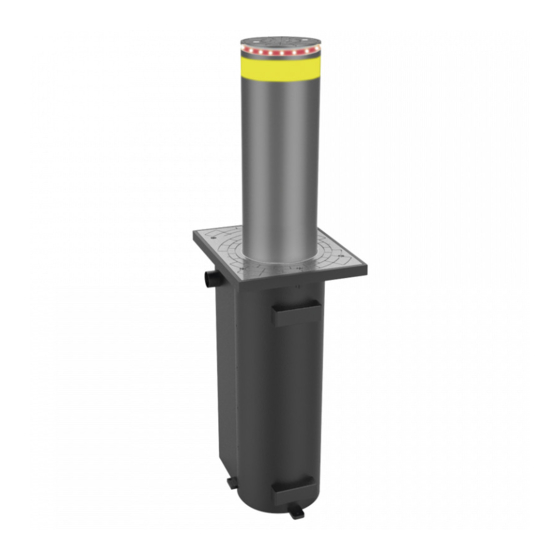
- Page 3 TECHNICAL DATASHEET OF HYDRAULIC DBO-275/P-600 – FE 6 mm hydraulic Drive Driven cylinder Steel FE 37 – thickness 6 mm Treatment undergone by driven cylinder Polyester powder painting- color grey anthracite Driven cylinder diameter 275 mm. Driven cylinder run 600mm Cylinder top(head) Anticorodal cemented alluminium Treatment undergone by cylinder top...
- Page 4 AUTOMATIC INDUSTRIAL by AccessPRO BOLLARD 275/P 600A INSTALLATION SEQUENCE 1) Ensure that the laying point of the AccessPRO Bollard does not fall within an impluvium area; in cases when, no matter why, this circumstance occurs, you need to partially shelter the AccessPRO Bollard by means of a draining channel, equipped with covering grid.
- Page 5 P. S.1: all tubes and steel reinforcements FeB44K must be set in full compliance with the regulations in force P.S. 2: all materials used for foundation, steel FeB44K and cls RCK= 25,00 n/mm ,must be certified and controlled in works as per certificate of quality released from producing firms in full compliance with the regulations in force.
- Page 6 DlS. P275_.SC06 G AccesPRO XB275H07K -AUTOMA BOllARD OKE=600 INSTA l lATJON PlA . N WJTH ' TH. E .METAlUC PJT © HErAU.IC Plr , C OUNTERFR'AHE SPIRIT t.EVB.. FLEXIBLE SHEA TH (J-4() R.EXSLE REFERENCE FOR TIE fJIRECTION .fJF THE COUNTERF�AHE l!JSTALLA r10N INDUSTRIAL by�PRO...
- Page 7 P275_SC07 _INE AccesPRO XB275H07K-AUTOMA BOtlARD - SrOKE=600 INSTA lA TTON PLAN WJTH TH,EMETAlUC Pn --------r ��L_____ SHEA TH d-.4() ..-· .. ------------... ·-·--. -� ..-... ------------.... ------· 1 1 1 1 1 1 I" I" 1, ..... 1 1 111 ••• 11111 1 r r 1 1 r 1 ..... 1 t •• r 1 1 1 1 1 1 1 •••• a :::::::::::::�·:::;::::��: �...
- Page 8 lexible scheath INDUSTRIAL 040mm by�PRO...
- Page 9 1800 OOl.tTIVE Loo> • 1400 1400 INIU:TIVE L!IJ> XB275H06K �...
- Page 10 lli. TMlllf XB275H07K...
- Page 11 NOTES ON MAKING THE MAGNETIC LOOP WITH A 9 m CABLE If using the automatic AccessPRO bollard, two inductive magnetic loops must be created to detect metal weights (cars), one in front of and another behind the bollard. The standard dimensions of these loops is: width 1.80 m - length 3.00 m.
- Page 12 INDUSTRIAL Acces.5PRO INSTALLATIONS SE UENCE ACCESSPRO BOL½R_Q_ �...
- Page 13 Max. 16 AccessPRO units featuring units to be connected to the simultaneous movement – The 1st control station AccessPRO unit is connected to the master unit – the others are connected to additional slave units – the size of the container is a...
- Page 14 Number on the terminal Box...
- Page 15 Number on the Number on the terminal Box Control panel Note: Between Bollard and control panel, three cable is necessity. ① Cable 1 : One RVVP 4*0.5 for Limit signal input. ② Cable 2 : One RVV 8*0.75 for DC 24V output. ③...
- Page 16 Communication : ① One communicate cable(UTP-CAT.5E) between every control panel. ② Dial the right address: Main control panel ------0 Slave control panel-----from 1 to 15 ③ The Last Slave control panel need connect with a Resistance(120Ω /0.125W) ④ The loop detector、 Traffic Light、 control button、 fire alarm is only available on the main control panel(Address = 0).
- Page 18 AccessPRO ELECTRONIC CIRCUIT DIP-SWITCH FUNCTIONALITIES Foreword : the DIP-SWITCHES that are found on the AccessPRO electronic circuit board are useful to the technicians for a quick diagnostic during maintenance/ repair work of the AccessPRO systems. Indeed, in the event failures, instead of disconnecting the wires from the terminal strips, it proves to be more functional to cut out a part of the circuits through a proper positioning of the DIP-SWITCHES.
- Page 19 Automatic Lifting Enabled Bollard: High Position After the Actuation of the drive No car pass the control passage. Bollard: Low Position Wait after 40s. The Car pass the control Passage (with safety device) Lifting Automatically Lifting Automatic Position ON = Automatic Lifting Inhibited : the Bollard lift , after actuating the drive for the first time, moves from high to low –...
- Page 20 Position OFF = Reversal Pressure Switch Inhibited : the function described above is inhibited – if the AccessPRO Bollard does not rise or during the rising stage it moves back with no apparent reason, the technician, on intervening, may temporarily inhibit this function to check whether the cause of the failure is to be ascribed to the pressure switch.
- Page 21 Ordinary Routine Maintenance Procedure For AccessPRO Bollard The standard routine maintenance sequence is as follows: Cleaning of pit with suction of all material settlements Cleaning of water drains located on the pit bottom Cleaning and greasing of the central sliding rail ...
Need help?
Do you have a question about the Industrial XB275H07K and is the answer not in the manual?
Questions and answers