
Summary of Contents for Intracom OSDR
- Page 1 OSDR Outdoor Software-Defined Radio (OSDR) platform Installation & Cabling Manual Edition 3.0 Confidential...
- Page 2 Information as well as drawings and specifications contained in this document are subject to change without prior notice. All trademarks and copyrights mentioned herein are the property of INTRACOM S.A. TELECOM SOLUTIONS and/or their respective owners. Any rights not expressly granted herein are reserved.
- Page 3 Outdoor Software Defined Radio (OSDR) platform Installation & Cabling Manual - Edition 3.0 Document Revision History Previous Edition: Current Edition: Reasons of Change M = Modified, A = Added, R = Removed Details • Sectoral 26/28/32 GHz antenna New materials (M) (A) •...
- Page 4 Outdoor Software Defined Radio (OSDR) platform Installation & Cabling Manual - Edition 3.0 -II-...
- Page 5 Outdoor Software Defined Radio (OSDR) platform Installation & Cabling Manual - Edition 3.0 Equipment Disposal Disposal of old electrical and electronic equipment (applicable through the European Union and other European countries with separate waste collection systems). This symbol, found on this product and any of its parts or on its operating instructions or on its packaging, indicates that electrical and electronic equipment may not be disposed of as unsorted municipal waste.
- Page 6 The full text of the EU declaration of conformity is available at the following URL: http://emc.intracom-telecom.com/en/start.htm ∆ήλωση Συμμόρφωσης Με την παρούσα, η Intracom Α.Ε. Τηλεπικοινωνιακών Λύσεων δηλώνει ότι τα προϊόντα OmniBAS φέρουν την σήμανση CE & WiBAS συμμορφούμενο προς τις απαιτήσεις και τις λοιπές διατάξεις των οδηγιών...
-
Page 7: Table Of Contents
Outdoor Software Defined Radio (OSDR) platform Installation & Cabling Manual - Edition 3.0 Table of Contents 1. Introduction ......................... 3 About this Document ......................3 Safety Precautions ......................5 2. Materials ..........................9 OSDR ..........................10 Antennas .......................... 11 Mounting Kits ........................12 Cables .......................... - Page 8 Table of Contents Indoor AC POE....................... 112 Appendix D: Cables Termination ..................114 Ethernet Cable ....................... 115 Grounding Cable ......................120 AC Power Supply Cable ....................123 Appendix E: Sectoral Antenna Pole Space Requirements ..........126 10.5 GHz Antenna ......................126 26/28/32 GHz Antenna ....................
-
Page 9: Introduction
About this Document Scope of The scope of this document is to provide detailed instructions on the Document installation and cabling of OSDR (Outdoor Software-Defined Radio platform) wireless product. This document applies for installation of all available operation modes: PtMP Hub... - Page 10 1. Introduction About this Document , Continued Conventions This document applies to the following conventions: Arial Bold blue • fonts are used for order codes. • Arial Blue underline fonts are used for document references. • Arial Bold black fonts are used for indicating important information or paragraph header.
-
Page 11: Safety Precautions
The values of the table are given for OSDR at max power and max gain 60 cm terminal antenna. BAND (GHz) - Page 12 • INTRACOM S.A. TELECOM SOLUTIONS and its resellers or distributors are not liable for injury, damage or violation of regulations associated with the installation of outdoor units or antennas.
- Page 13 Installation & Cabling Manual - Edition 3.0 Safety Precautions , Continued Proper Grounding Installation & Equipotential Bonding Never power on OSDR equipment unless you have completed the grounding installation. There is risk of equipment failure and / or electrical shock. Ensure that: •...
- Page 14 (powering through power injector). There is risk of radio unit failure. Always ensure that the power supply source / power injector is OFF before plugging / unplugging. Laser Radiation When using SFP, then the OSDR is a CLASS 1 laser product.
-
Page 15: Materials
Outdoor Software Defined Radio (OSDR) platform Installation & Cabling Manual - Edition 3.0 2. Materials Scope This chapter describes all the available materials for OSDR installation. Topics The chapter includes the following topics: Description Page OSDR Antennas Mounting Kits Cables... -
Page 16: Osdr
2. Materials OSDR Radio unit Oder Code Description Full outdoor software defined radio, 10.5/26/28/32 GHz, FDD, GbE. OSDR-OB-U-DSDS-SB Operation Modes: PtMP Hub, PtMP TS, PtP Node. -
Page 17: Antennas
Outdoor Software Defined Radio (OSDR) platform Installation & Cabling Manual - Edition 3.0 Antennas Antenna types Photo Description Antenna, sectoral 90 , integrated, 26/28/32 GHz. Includes: • Mounting kit. • Greasing paste. • Installation leaflet. Antenna, sectoral 90 , integrated, 10.5 GHz. -
Page 18: Mounting Kits
2. Materials Mounting Kits Mounting kit for panel antenna Oder Code Description OSDR-ANT-MNT Pole/Wall mounting kit for panel antenna 10.5 GHz (pole diameter 48 mm up to 60 mm). Pole adaptation Oder Code Description bracket for INST-ADAPT Pole adaptation bracket for panel antenna 10.5 GHz (pole panel antenna diameter 61 mm up to 120 mm). - Page 19 Outdoor Software Defined Radio (OSDR) platform Installation & Cabling Manual - Edition 3.0 Mounting Kits , Continued Hooks for panel antenna Oder Code Description OSDR-PL-ANT-KIT Hooks for panel antenna 10.5 GHz. Pole mounting bracket for outdoor DC PoNE Oder Code...
- Page 20 2. Materials Mounting Kits , Continued ETH-SRG-OD68 Pole hose Stainless steel hose clamp for pole installation of lightning ETH-SRG-OD68 clamps surge protector (one requires 2 clamps). The following table shows the available hose clamps: Item Order Code Description ∅ 64-140 mm, width = 14.2 mm. ST-CL64-140 For ∅...
-
Page 21: Cables
Outdoor Software Defined Radio (OSDR) platform Installation & Cabling Manual - Edition 3.0 Cables RSSI cable Order Code / Photo Description CAB-RSSI-BNC RSSI cable, male BNC to 2 x banana plugs, 75 Ω for measuring OSDR receive signal level in volts (voltmeter is required). - Page 22 2. Materials Cables , Continued Power supply Order Code / Photo Description cables for AC-PWR-CAB AC power bulk cable , 3 x 0.75 mm , 0.6 / 1 kV, outdoor power stranded, UV-rated, industrial type, outdoor use, injectors per meter. Used for powering of outdoor AC PoNE (PONE- OD67-AC).
- Page 23 Outdoor Software Defined Radio (OSDR) platform Installation & Cabling Manual - Edition 3.0 Cables , Continued Fiber optic Prefabricated connectorized fiber optic cables for outdoor use, DX, 2 x cables LC/PC-LC/PC, available in multi-mode (MM) & single mode (SM) in different lengths.
-
Page 24: Cable Glands And Holder
2. Materials Cable Glands and Holder M20 and M25 Order Code / Photo Details glands and M20-GLAND OSDR M20 gland for holders Ethernet cable. OSDR-HOLD-2 Cable holder for fastening M20-GNAND (includes 2 x tie wraps: L = 100 mm, D = 18 mm, W = 2.5 mm). -
Page 25: Power Injectors
Outdoor Software Defined Radio (OSDR) platform Installation & Cabling Manual - Edition 3.0 Power Injectors Indoor power Order Code / Photo Description injectors POE-AC75-ID Indoor AC POE – 75 W (Wall installation materials are not included). POE-ID-AC72 Indoor AC POE – 72 W (Wall installation materials are not included). - Page 26 2. Materials Power Injectors , Continued Outdoor power Order Code / Photo Description injectors PONE-OD-DC Outdoor DC PoNE – 60 W • For wall installation the package includes: − 4 x screws and wall plugs. − 1 x M4 grounding terminal (for terminating 6 mm grounding cable GND-CAB6-ID...
-
Page 27: Sfp
Outdoor Software Defined Radio (OSDR) platform Installation & Cabling Manual - Edition 3.0 Electrical SFP Oder Code / Photo Description module SFP-ELGFE-IN Electrical SFP for 10/100/1000 Base-T operation. Optical SFP module Order Code Description SFP-MM-500M SFP, multi-mode, up to 500 m, 1.25 Gbit/s, 850 nm. -
Page 28: Ancillaries
2. Materials Ancillaries Others Item Order Code / Photo Description CAB-TIE-UV Cable tie, 500 x 12.5 mm, black, UV-resistant. One tie is recommended per cable meter. ST-RJ45 RJ-45 connector, shielded for S-FTP cable termination (ETH-CAB-SFTP). ETH-SRG-OD68 Outdoor lightning surge protector with IP68 ETH- ingress protection for Ethernet lines (one SRG-OD68... -
Page 29: Others
Item Order Code / Photo Description CRIMP-TOOL-S Hand crimping tool for RJ-45 connector (ST-RJ45). TOOL-M20 Optional tool for M20 gland. Used for installation of: • OSDR 2 x M20 glands side-by-side • Outdoor AC power injector (PONE- OD67-AC) M20 gland. -
Page 30: Before Starting The Installation
3. Before Starting the Installation 3. Before Starting the Installation Scope This chapter describes all the prerequisites that must be considered prior to installing the OSDR equipment. Topics The chapter includes the following topics: Description Page Radio Unit View Radio Unit Cabling... -
Page 31: Radio Unit View
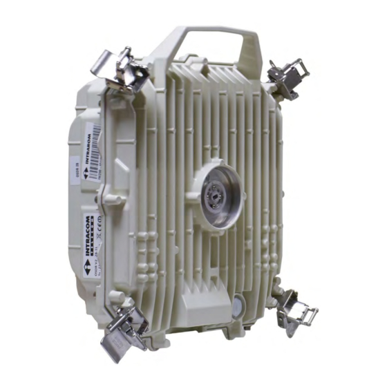
Outdoor Software Defined Radio (OSDR) platform Installation & Cabling Manual - Edition 3.0 3.1. Radio Unit View Receptacles Marking Description GbE2 Gigabit Ethernet, To connect Ethernet (S-FTP) cable Electrical RJ-45 for traffic / inband management (100/1000 Base-T). and power via power injector. - Page 32 3. Before Starting the Installation Radio Unit View , Continued Label Description Product description. Frequency band. OSDR determination as Low or High in the link pair. Duplex spacing (MHz). Sub-band (01 up to 18). Transmit frequencies. Receive frequencies. Continued on next page...
- Page 33 Outdoor Software Defined Radio (OSDR) platform Installation & Cabling Manual - Edition 3.0 Radio Unit View , Continued Other points Marking Description Anchor point To carry OSDR unit. Wave guide To install antenna feeder. Clamps To mount antenna. Female threads for M5 To install mounting kit for panel screws.
-
Page 34: Radio Unit Cabling
3. Before Starting the Installation 3.2. Radio Unit Cabling Introduction This topic describes the cabling overview, as follows: Description Page Gigabit ETH cable for service Traffic, Inband Management and Powering Fiber Optic cable for service Traffic and Inband Management / Gigabit Ethernet (S-FTP) cable for service Powering The following instructions refers to cabling overview without using any additional device for lightning surge protection. -
Page 35: Gigabit Eth Cable For Service Traffic, Inband Management And Powering
The Gigabit Ethernet (S-FTP) cable for service traffic, inband management restriction and external powering applies to the following restriction: The maximum length of Gigabit Ethernet (S-FTP) cable (Cat5E or Cat6), between OSDR receptacle (GbE2) and customer network receptacle cannot exceed 100 meters. Continued on next page... - Page 36 3. Before Starting the Installation Gigabit ETH cable for service Traffic, Inband Management and Powering , Continued Cabling The following schematic shows a cabling overview of OSDR radio unit when overview using powering is through an indoor AC POE (75W): AC POE Marking...
- Page 37 Installation & Cabling Manual - Edition 3.0 Gigabit ETH cable for service Traffic, Inband Management and Powering , Continued Cabling The following schematic shows a cabling overview of OSDR radio unit when overview using powering is through an indoor AC POE (72W): AC POE, continued...
- Page 38 3. Before Starting the Installation Gigabit ETH cable for service Traffic, Inband Management and Powering , Continued Cabling The following schematic shows a cabling overview of OSDR radio unit when overview using powering is through an indoor AC POE (56W): AC POE, continued...
- Page 39 Installation & Cabling Manual - Edition 3.0 Gigabit ETH cable for service Traffic, Inband Management and Powering , Continued Cabling The following schematic shows a cabling overview of OSDR radio unit when overview using powering is through an outdoor DC PoNE: DC PoNE Marking...
- Page 40 3. Before Starting the Installation Gigabit ETH cable for service Traffic, Inband Management and Powering , Continued Cabling The following schematic shows a cabling overview of OSDR radio unit when overview using powering is through an outdoor AC PoNE: DC PoNE, continued...
- Page 41 Installation & Cabling Manual - Edition 3.0 Gigabit ETH cable for service Traffic, Inband Management and Powering , Continued Cabling The following schematic shows a cabling overview of OSDR radio unit when overview using powering is through an indoor OmniBAS 4W/8W: DC PoNE,...
- Page 42 3. Before Starting the Installation Gigabit ETH cable for service Traffic, Inband Management and Powering , Continued Cabling The following schematic shows a cabling overview of OSDR radio unit when overview using powering is through an indoor OmniBAS DC PoNE, continued...
-
Page 43: Fiber Optic Cable For Service Traffic And Inband Management / Gigabit Ethernet (S-Ftp) Cable For Service Powering
Outdoor Software Defined Radio (OSDR) platform Installation & Cabling Manual - Edition 3.0 Fiber Optic cable for service Traffic and Inband Management / Gigabit Ethernet (S-FTP) cable for service Powering Fiber optic The following tables shows the maximum length of optical fiber cables in... - Page 44 The maximum length of Gigabit Ethernet (S-FTP) cable (Cat5E or Cat6), restriction – between OSDR receptacle (GbE2 or FE) and power injector receptacle when AC POE (POE or OUT) cannot exceed 200 meters (1 x 200 meter cable). is used...
- Page 45 Fiber Optic cable for service Traffic and Inband Management / Gigabit Ethernet (S-FTP) cable for service Powering , Continued Cabling The following schematic shows a cabling overview of OSDR radio unit when overview using powering is through an indoor AC POE (75W): AC POE...
- Page 46 Fiber Optic cable for service Traffic and Inband Management / Gigabit Ethernet (S-FTP) cable for service Powering , Continued Cabling The following schematic shows a cabling overview of OSDR radio unit when overview using powering is through an indoor AC POE (72W): AC POE,...
- Page 47 Fiber Optic cable for service Traffic and Inband Management / Gigabit Ethernet (S-FTP) cable for service Powering , Continued Cabling The following schematic shows a cabling overview of OSDR radio unit when overview using powering is through an indoor AC POE (56W): AC POE,...
- Page 48 Fiber Optic cable for service Traffic and Inband Management / Gigabit Ethernet (S-FTP) cable for service Powering , Continued Cabling The following schematic shows a cabling overview of OSDR radio unit when overview using powering is through an outdoor DC PoNE: DC PoNE...
- Page 49 Fiber Optic cable for service Traffic and Inband Management / Gigabit Ethernet (S-FTP) cable for service Powering , Continued Cabling The following schematic shows a cabling overview of OSDR radio unit when overview using powering is through an indoor OmniBAS 4W/8W:...
- Page 50 Fiber Optic cable for service Traffic and Inband Management / Gigabit Ethernet (S-FTP) cable for service Powering , Continued Cabling The following schematic shows a cabling overview of OSDR radio unit when overview using powering is through an indoor OmniBAS DC PoNE,...
-
Page 51: Installation Tools
Outdoor Software Defined Radio (OSDR) platform Installation & Cabling Manual - Edition 3.0 3.3. Installation Tools Prerequisites It is installer responsibility to provide the tools for equipment installation. Equipment Item Tool / Photo Description installation Adjustable torque U-wrench tool (up to 29 mm opening and supporting max tightening torque 40 Nm). - Page 52 3. Before Starting the Installation Installation Tools , Continued Cables Type of cables to be terminated: Termination • Ethernet (S-FTP) cable. • AC & DC power supply cables for outdoor power injectors. • 6mm and 16 mm outdoor yellow/green grounding cables. Item Tool / Photo Description...
-
Page 53: Site Prerequisites
Outdoor Software Defined Radio (OSDR) platform Installation & Cabling Manual - Edition 3.0 3.4. Site Prerequisites Site survey Site survey should be done before start the installation taking in consideration the following: Premises information • Site details (address, contact persons, GPS and/or map co-ordinates, etc.). - Page 54 3. Before Starting the Installation Site Prerequisites , Continued Preparation of • Access to the installation premises must be facilitated during the the installation installation period. premises • Entrances must be large enough to enable the easy transportation of the new equipment.
- Page 55 Outdoor Software Defined Radio (OSDR) platform Installation & Cabling Manual - Edition 3.0 Site Prerequisites , Continued Lightning & Surge protection A: For Ethernet (S-FTP) Cables: Lighting surge protection device (LSP) is required to minimize possibility of equipment damage to any equipment connected to the unit from lighting induced surges.
- Page 56 3. Before Starting the Installation Site Prerequisites , Continued Pole • The pole construction should be rust free and strong enough to handle the installation weight and restrict movement due to air pressure. • Should be perfectly perpendicular to allow correct alignment of the antenna.
-
Page 57: Installation Procedures
Outdoor Software Defined Radio (OSDR) platform Installation & Cabling Manual - Edition 3.0 4. Installation Procedures Installation This chapter describes the mechanical installation and cabling of the OSDR procedure equipment. overview The following tables shows with order all the necessary steps for installation... -
Page 58: Radio Unit And Antenna
4.1. Radio Unit and Antenna Sectoral and Parabolic Antenna Introduction Apply this procedure for installing the OSDR to sectoral/parabolic antenna. For sectoral antennas the procedure includes the alignment steps, also. The antenna is capable to be installed in both side of the pole. The following photos are indicative of the installation in the left orientation of the sectoral/parabolic models. - Page 59 Outdoor Software Defined Radio (OSDR) platform Installation & Cabling Manual - Edition 3.0 Sectoral and Parabolic Antenna , Continued Procedure To install the OSDR onto the sectoral/parabolic antenna and to perform antenna alignment, proceed as follows: Step Action The antenna installation should look as follows.
- Page 60 4. Installation Procedures Sectoral and Parabolic Antenna , Continued Procedure, Step Action continued Remove antenna protection label from the feeder, as shown below. Continued on next page...
- Page 61 If the LINK polarization is HORIZONTAL, use the allen key to loosen the four screws at the waveguide port of the OSDR (do not remove the screws) and then TURN the polarizer, as shown below: How to change antenna polarization refer to antenna installation leaflet.
- Page 62 • For sectoral antenna 26/28/32 GHz go to step 8. • For sectoral antenna 10.5 GHz go to step 19. Unlock the four clamps of the radio unit,, as shown below. Mount the OSDR onto the antenna, as shown below. Continued on next page...
- Page 63 Outdoor Software Defined Radio (OSDR) platform Installation & Cabling Manual - Edition 3.0 Sectoral and Parabolic Antenna , Continued Procedure, Step Action continued Lock and secure all four clamps according to the pattern below. Details of Clamps closing End of procedure for parabolic antenna.
- Page 64 4. Installation Procedures Sectoral and Parabolic Antenna , Continued Procedure, continued Step Action Perform the following actions: A: Mount the tool onto the antenna radio wave feeder, as shown below. Do not over tighten. B: Use the cross screwdriver to screw the bolts and then fully tighten.
- Page 65 Procedure, continued Step Action Use the U-wrench key (13 mm) to loosen the 3 nuts, as shown below (do not remove the nuts). Install the OSDR onto the antenna as described to steps 5, 6 and 7. Continued on next page...
- Page 66 A: Place the inclinometer, as shown below: B: Rotate (left-right) the radio unit till the inclinometer digital indicator reaches 0 degrees. Remove the OSDR. Tighten the three M10 nuts (see step 9). DO NOT remove the XPOL tool. • Do not over tighten.
- Page 67 Procedure, continued Step Action Install the OSDR onto the antenna as described to steps 5, 6 and 7. To correct the elevation angle for matching with the RF planning data, perform the following actions: A: Place the inclinometer, as shown below.
- Page 68 Step Action Remove the OSDR and the XPOL tool. Install the OSDR onto the antenna as described to steps 5, 6 and 7. Use the U-wrench tool to perform azimuth adjustment , as shown below. • Do not over tighten.
- Page 69 Procedure, continued Step Action Install the OSDR onto the antenna as described to steps 5, 6 and 7. To correct the elevation angle for matching with the RF planning data, perform the following actions: A: Place the inclinometer, as shown below.
- Page 70 4. Installation Procedures Sectoral and Parabolic Antenna , Continued Procedure, continued Step Action Use the U-wrench tool to perform azimuth adjustment , as shown below. • Do not over tighten. • For maximum tightening torque please follow the antenna installation leaflet (available in package).
-
Page 71: Panel Antenna
Outdoor Software Defined Radio (OSDR) platform Installation & Cabling Manual - Edition 3.0 Panel Antenna Introduction This topic describes the following procedures: Description See Page Mounting kit installation procedure Panel antenna installation procedure Tools and Description materials • Adjustable torque U-wrench. - Page 72 4. Installation Procedures Panel Antenna , Continued Mounting kit To install the mounting kit, proceed as follows: installation procedure Step Action Perform the following actions: A: Unscrew the azimuth adjuster screw. B: Release the u-bolts. Place the arm bracket to the pole and install the two U-bolts, as shown below.
- Page 73 Perform the following actions: A: Unscrew the four screws. B: Place the radio mounting adapter onto the OSDR, as shown below. C: Install and screw the four screws. Do not over tighten. Adjust the tool for max tightening torque 4.2 Nm.
- Page 74 4. Installation Procedures Panel Antenna , Continued Mounting kit installation Step Action procedure, Insert arm into the arm bracket, as shown below. continued Continued on next page...
- Page 75 Outdoor Software Defined Radio (OSDR) platform Installation & Cabling Manual - Edition 3.0 Panel Antenna , Continued Mounting kit installation procedure, continued Step Action Perform the following actions: A: Install the azimuth adjuster (taking into account the caution), as shown below.
- Page 76 4. Installation Procedures Panel Antenna , Continued Mounting kit installation procedure, continued Step Action Use the adjustable wrench to fully tighten the adjuster bolt. Do not over tighten. Adjust the tool for max tightening torque 20 Nm. The installation should look as follows. End of procedure.
- Page 77 Outdoor Software Defined Radio (OSDR) platform Installation & Cabling Manual - Edition 3.0 Panel Antenna , Continued Panel antenna To install the panel antenna to OSDR, proceed as follows: installation procedure Step Action Install the antenna hooks (x 4), as shown below.
- Page 78 4. Installation Procedures Panel Antenna , Continued Panel antenna installation procedure, continued Step Action Radio unit and antenna should be adjusted for common polarization. If the LINK HORIZONTAL polarization is then the feeders should be remained, as shown below: If the LINK polarization is VERTICAL, use the allen key to loosen the four screws at the waveguide port of the radio (do not remove the screws) and then TURN the polarizer, as shown below: The terminal station polarization at 10.5 GHz (radio-panel antenna) is specific and...
- Page 79 Outdoor Software Defined Radio (OSDR) platform Installation & Cabling Manual - Edition 3.0 Panel Antenna , Continued Panel antenna installation Step Action procedure, Perform the following actions: continued A: Lubricate the O-ring with silicone grease. B: Remove antenna protection plastic sticker from the feeder.
- Page 80 4. Installation Procedures Panel Antenna , Continued Panel antenna installation Step Action procedure, Mount the panel antenna onto the OSDR, as shown below. continued Continued on next page...
- Page 81 Outdoor Software Defined Radio (OSDR) platform Installation & Cabling Manual - Edition 3.0 Panel Antenna , Continued Panel antenna installation Step Action procedure, Lock and secure all four clamps according to the pattern below. continued Details of Clamps closing End of procedure...
-
Page 82: Radio Unit Grounding Cable
4. Installation Procedures 4.2. Radio Unit Grounding Cable Introduction Apply this procedure for installing the grounding cable to OSDR grounding terminal. Prerequisites How to terminate a grounding cable please refer to Appendix D: Cables Termination. Tools and Description materials Tools Adjustable torque U-wrench. -
Page 83: Radio Unit Ethernet (S-Ftp) Cable
Outdoor Software Defined Radio (OSDR) platform Installation & Cabling Manual - Edition 3.0 4.3. Radio Unit Ethernet (S-FTP) Cable Introduction Apply this procedure for installing the Ethernet (S-FTP) cable with M20 gland to OSDR receptacle (GbE2 or FE). Prerequisites How to terminate an Ethernet (S-FTP) cable please refer to... - Page 84 4. Installation Procedures Radio Unit Ethernet (S-FTP) Cable , Continued Procedure To install the Ethernet cable with M20 gland to OSDR receptacle (GbE2 or FE), proceed as follows: Step Action Remove the protective cap (plastic for GbE2 or metallic for FE).
- Page 85 , Continued Procedure, continued Step Action Plug the RJ-45 jack into the GbE2 port of the OSDR. Listen for a “click” when inserting. This verifies that the jack has been inserted properly. Perform the following actions: Do not over tighten. Adjust the...
- Page 86 4. Installation Procedures Radio Unit Ethernet (S-FTP) Cable , Continued Procedure, Step Action continued Perform the following actions: A: Insert the seal into “pressure fingers” of claw. B: Insert the O-ring. C: Screw the sealing nut. Use the adjustable torque U- wrench to fully tighten.
- Page 87 Outdoor Software Defined Radio (OSDR) platform Installation & Cabling Manual - Edition 3.0 Radio Unit Ethernet (S-FTP) Cable , Continued Procedure, Step Action continued Install the cable holder, as described to Radio Unit Cable Holder on page 88. End of procedure.
-
Page 88: Power Injector
4. Installation Procedures 4.4. Power Injector For power injectors installation refer to Appendix C: Power Injector Installation on page 96. -
Page 89: Radio Unit Optical Cable (Optional)
Adjustable torque U-wrench. • M25-GLAND. Materials • Fiber Optic cable. • SFP module. Procedure To install the Fiber Optic cable with M25 gland to OSDR receptacle (GbE1), proceed as follows: Step Action Remove the metallic protective cap. M25-GLAND Disassemble the parts, as shown below. - Page 90 Perform the following actions: Install the fiber optic cable into the SFP module. Plug the SFP module into the OSDR SFP cage. Install the body extension. Do not over tighten. Adjust the tool for max tightening torque 10 Nm.
- Page 91 Outdoor Software Defined Radio (OSDR) platform Installation & Cabling Manual - Edition 3.0 Radio Unit Optical Cable (Optional) , Continued Procedure, continued Step Action Perform the following actions: Do not over tighten. Adjust the A: Screw the body into the body tool for max tightening torque extension thread.
- Page 92 4. Installation Procedures Radio Unit Optical Cable (Optional) , Continued Procedure, continued Step Action Perform the following actions: A: Insert the seal into “pressure fingers” of claw. B: Insert the O-ring. C: Screw the sealing nut. Use the adjustable torque U-wrench to fully tighten. The ring protects from overtightening.
- Page 93 Outdoor Software Defined Radio (OSDR) platform Installation & Cabling Manual - Edition 3.0 Radio Unit Optical Cable (Optional) , Continued Procedure, continued Step Action Install the cable holder, as described to Radio Unit Cable Holder on page 88. End of procedure.
-
Page 94: Radio Unit Cable Holder
4. Installation Procedures 4.6. Radio Unit Cable Holder Introduction Apply this procedure for installing the cable holder to OSDR. Tools and Description materials Tools Adjustable torque wrench with hexagon male bit OSDR-HOLD-2 OSDR-HOLD-5 Materials Procedure To install the cable holder, proceed as follows:... - Page 95 Outdoor Software Defined Radio (OSDR) platform Installation & Cabling Manual - Edition 3.0 Radio Unit Cable Holder , Continued Procedure, Step Action continued Perform the following: A: Attach the holder to radio. B: Use the tool to install the three lock washers and screws, as shown below.
- Page 96 4. Installation Procedures Radio Unit Cable Holder , Continued Procedure, Step Action continued Use the tie wraps to tighten the cable, as shown below. End of procedure. Do not forget to install the OSDR grounding cable.
-
Page 97: Appendix A: Adaptation Kit Installation
Outdoor Software Defined Radio (OSDR) platform Installation & Cabling Manual - Edition 3.0 Appendix A: Adaptation Kit Installation Pole Installation Introduction Apply this procedure for installing the adaptation kit onto the pole. Tools and Description materials • Adjustable torque U-wrench. - Page 98 Appendix A: Adaptation Kit Installation Pole Installation , Continued Procedure To install adaptation kit onto the pole, proceed as follows: Step Action Choose the proper hose clamps based on the pole diameter. Pass through the clamps to bracket, as shown below: Choose the correct position onto the pole to install the adaptation bracket.
- Page 99 Outdoor Software Defined Radio (OSDR) platform Installation & Cabling Manual - Edition 3.0 Pole Installation , Continued Procedure, Step Action continued Install the arm bracket onto the adaptation bracket, as shown below. Do not over tighten. Adjust the tool for max tightening torque 15 Nm.
-
Page 100: Appendix B: Mounting Kit Wall Installation
Apply this procedure for installing the mounting kit onto the wall. Tools and Description materials Tools Adjustable torque U-wrench. OSDR-ANT-MNT. Materials Procedure To install radio unit to sectoral/parabolic antenna, proceed as follows: Step Action Use a drilling machine (fitted with an 8 mm drill bit) and the following drill template to drill the holes in the wall surface, as shown below. - Page 101 Outdoor Software Defined Radio (OSDR) platform Installation & Cabling Manual - Edition 3.0 Wall Installation , Continued Procedure, Step Action continued Insert items (W, A, J, I X) with order, as shown below: The items X, W listed below are not provided:...
-
Page 102: Appendix C: Power Injector Installation
Appendix C: Power Injector Installation Appendix C: Power Injector Installation Topics The chapter includes the following topics: Description See Page Outdoor DC PoNE Outdoor AC PoNE Indoor AC POE... -
Page 103: Outdoor Dc Pone
41.7 V for Cat5E then the length of Gigabit Ethernet (S-FTP) cable S-FTP cable (Cat5E or Cat6), between OSDR receptacles and PoNE receptacles , length cannot reach more than 100 meters. The following table shows the maximum S-FTP cable length versus the... - Page 104 Appendix C: Power Injector Installation Outdoor DC PoNE , Continued Connection diagram Description DC power supply cable. Single pole Circuit. Local DC power distributor. Continued on next page...
- Page 105 Outdoor Software Defined Radio (OSDR) platform Installation & Cabling Manual - Edition 3.0 Outdoor DC PoNE , Continued Equipment overview Marking Details Gbe IN / Gbe IN: To connect the Gigabit Gigabit Ethernet Gbe OUT 100/1000 Base-T, Ethernet (S-FTP) cable for Electrical (RJ-45).
- Page 106 Appendix C: Power Injector Installation Outdoor DC PoNE , Continued Tools and Description materials Tools Adjustable torque wrench with all bits. • INST-PONE-PL. Materials • PONE-OD-DC. • Ethernet (S-FTP) cable terminated to RJ-45 jack. • Grounding cable terminated to 6 mm lug.
- Page 107 Outdoor Software Defined Radio (OSDR) platform Installation & Cabling Manual - Edition 3.0 Outdoor DC PoNE , Continued Pole and wall For mechanical installation and cabling of outdoor DC PonE, proceed as installation follows: procedure Step Action Pole installation: Attach the plate onto rear side of PonE, as shown below.
- Page 108 Appendix C: Power Injector Installation Outdoor DC PoNE , Continued Pole and wall installation procedure, continued Step Action Prepare and terminate the Ethernet cables (x 2) as instructed to Appendix D: Cables Termination on page 114. Install the Ethernet cables, as follows: Use the tool with TORX T10 bit to remove the clamp screw.
- Page 109 Outdoor Software Defined Radio (OSDR) platform Installation & Cabling Manual - Edition 3.0 Outdoor DC PoNE , Continued Pole and wall installation procedure, continued Step Action Prepare and terminate the grounding cable as instructed to Appendix D: Cables Termination. Use the tool with TORX T10 bit to install the grounding cable, as shown below.
- Page 110 Appendix C: Power Injector Installation Outdoor DC PoNE , Continued Pole and wall installation procedure, continued Step Action Switch-off the local DC power source & the circuit breaker (between PoNE and the local DC power source). Install the power supply cable, as follows: Connect the power cable to the local DC power source (Brown wire: +V, blue wire: -V).
-
Page 111: Outdoor Ac Pone
Outdoor Software Defined Radio (OSDR) platform Installation & Cabling Manual - Edition 3.0 Outdoor AC PoNE Introduction Apply this procedure for installing the outdoor AC PoNE onto the pole and wall. Equipment overview Marking Details Grounding point. To connect the grounding cable. - Page 112 Appendix C: Power Injector Installation Outdoor AC PoNE , Continued Tools and Description materials • Adjustable torque U-wrench. Tools • TOOL-M20. • INST-PONE-PL2. Materials • PONE-OD67-AC. • Ethernet (S-FTP) cable terminated to RJ-45 jack. • Grounding cable terminated to 16 mm lug.
- Page 113 Outdoor Software Defined Radio (OSDR) platform Installation & Cabling Manual - Edition 3.0 Outdoor AC PoNE , Continued Pole and wall For mechanical installation and cabling of outdoor AC PoNE, proceed as installation follows: procedure Step Action Prepare and terminate the Ethernet cables (x 2) as instructed to...
- Page 114 Appendix C: Power Injector Installation Outdoor AC PoNE , Continued Pole and wall installation procedure, continued Step Action Perform the following: Insert the claw to body taking in consideration the caution below. Insert the seal to claw. C: Use the adjustable torque U-wrench to screw the sealing nut to body. Do not over tighten.
- Page 115 Outdoor Software Defined Radio (OSDR) platform Installation & Cabling Manual - Edition 3.0 Outdoor AC PoNE , Continued Pole and wall installation procedure, continued Step Action Perform the following: Set both keys over the sealing nut as shown below. Use the hexagon 24 mm tool to prevent the body receptacle from rotating and loosening.
- Page 116 Appendix C: Power Injector Installation Outdoor AC PoNE , Continued Pole and wall installation procedure, continued Step Action Prepare and terminate the grounding cable as instructed to Appendix D: Cables Termination. Install the grounding cable as shown below. Do not over tighten. Adjust the tool with M5 deep socket for maximum tightening torque 3 Nm.
- Page 117 Outdoor Software Defined Radio (OSDR) platform Installation & Cabling Manual - Edition 3.0 Outdoor AC PoNE , Continued Pole and wall installation procedure, continued Step Action Wall installation: Perform the following actions: • Position the device on the wall surface and using a pencil mark the drill points.
-
Page 118: Indoor Ac Poe
Appendix C: Power Injector Installation Indoor AC POE Introduction Apply this procedure for installing the indoor AC POE onto the wall. Overview Marking Details INPUT 3-pins AC socket (EU). To connect the AC power supply cord. Multi-functioning LED. To provide radio unit status during operation. - Page 119 Outdoor Software Defined Radio (OSDR) platform Installation & Cabling Manual - Edition 3.0 Indoor AC POE , Continued Wall PoE is an indoor device only and can be installed as desktop or in a wall installation surface, as shown below:...
-
Page 120: Appendix D: Cables Termination
Appendix D: Cables Termination Appendix D: Cables Termination Topics The chapter includes the following topics: Description See Page Ethernet Cable Grounding Cable AC Power Supply Cable Tools and Description materials Tools Cables Termination on page ETH-CAB-SFTP terminated to ST-RJ45. Materials GND-KIT16-OD terminated to M5 terminal lug for 16 mm cable. -
Page 121: Ethernet Cable
Outdoor Software Defined Radio (OSDR) platform Installation & Cabling Manual - Edition 3.0 Ethernet Cable Introduction Apply this procedure for terminating an Ethernet (S-FTP) cable to RJ-45 connector (ST-RJ45). S-FTP cable The equipment to which you connect the cable requires a different way of overview cable termination. - Page 122 Appendix D: Cables Termination Ethernet Cable , Continued Ethernet cable To terminate the cable, proceed as follows: termination procedure Step Action Perform the following: For termination type A: Strip 40 mm of outer jacket. For termination type B: Strip 80 mm of outer jacket. Fold shield back (over the jacket).
- Page 123 Outdoor Software Defined Radio (OSDR) platform Installation & Cabling Manual - Edition 3.0 Ethernet Cable , Continued Ethernet cable termination Untwist wire pairs and arrange according to the T-568 standard procedure, straight-through cable, as shown below: continued Carefully insert the eight wires into the cavity of the wire guide so that its numbering is visible from the top.
- Page 124 Appendix D: Cables Termination Ethernet Cable , Continued Ethernet cable termination Step Action procedure, Perform the following: continued Fold back the crimping terminal of the connector. Fully insert wire guide and cable into the connector’s body until the shield (overlapping the jacket’s end) reaches the crimping position.
- Page 125 Outdoor Software Defined Radio (OSDR) platform Installation & Cabling Manual - Edition 3.0 Ethernet Cable , Continued Ethernet cable termination Step Action procedure With the pliers, bring the terminal of the connector back, over the (continued) exposed shield, and press gently around the terminal to form. This will achieve good contact with the shield.
-
Page 126: Grounding Cable
Grounding Cable Introduction Apply the procedures for terminating grounding cable to grounding lug of the following equipment: GROUNDING CABLE 6 mm 16 mm outdoor DC PoNE OSDR radio unit indoor AC POE 72 W outdoor AC PoNE Continued on next page... - Page 127 Repeat step 3 for the other end of the cable using the appropriate terminal lug. Eventually both ends should be as follows: • M5 grounding lug (OSDR or outdoor AC PoNE side). • Appropriate grounding lug (grounding bar side). End of procedure.
- Page 128 Appendix D: Cables Termination Grounding Cable , Continued Grounding To terminate the 6 mm grounding cable, proceed as follows: cable (6 mm termination Step Action procedure Cut the grounding cable (for 6 mm ) according to the distance between equipment and grounding bar. Use the blade to strip 1 cm from each end of the cable, as below: 1 cm 1 cm...
-
Page 129: Ac Power Supply Cable
Outdoor Software Defined Radio (OSDR) platform Installation & Cabling Manual - Edition 3.0 AC Power Supply Cable Introduction Apply this procedure for terminating AC power supply cable to AC power connector for outdoor AC PoNE. Continued on next page... - Page 130 Appendix D: Cables Termination AC Power Supply Cable , Continued Procedure To terminate the AC power supply cable to AC power connector of outdoor AC PoNE, proceed as follows: Step Action Perform the following actions: Strip approx. 10 mm from the cable’s outer sheath. Strip approx.
- Page 131 Outdoor Software Defined Radio (OSDR) platform Installation & Cabling Manual - Edition 3.0 AC Power Supply Cable , Continued Procedure, continued Step Action Assemble the connector by tightening the parts together, as shown below: End of procedure.
-
Page 132: Appendix E: Sectoral Antenna Pole Space Requirements
Appendix E: Sectoral Antenna Pole Space Requirements Appendix E: Sectoral Antenna Pole Space Requirements 10.5 GHz Antenna Elevation axis (in mm) Continued on next page... - Page 133 Outdoor Software Defined Radio (OSDR) platform Installation & Cabling Manual - Edition 3.0 10.5 GHz Antenna , Continued Azimuth axis (in mm)
-
Page 134: 26/28/32 Ghz Antenna
Appendix E: Sectoral Antenna Pole Space Requirements 26/28/32 GHz Antenna Elevation axis (in mm) Continued on next page... - Page 135 Outdoor Software Defined Radio (OSDR) platform Installation & Cabling Manual - Edition 3.0 26/28/32 GHz Antenna , Continued Azimuth axis (in mm)
-
Page 136: Appendix F: Receptacles Pin Out
Appendix F: Receptacles Pin Out Appendix F: Receptacles Pin Out Radio Unit Scope For Traffic / Power. Type RJ-45 Female (100/1000 Base-T electrical). Pin out Signal Description Transmit and Receive Data A+ Input / Output Transmit and Receive Data A- Input / Output Transmit and Receive Data B+ Input / Output... - Page 137 Outdoor Software Defined Radio (OSDR) platform Installation & Cabling Manual - Edition 3.0 Radio Unit , Continued Scope For GbE optical data traffic connection. Type SFP cage (1000 Base-X fiber).
-
Page 138: Outdoor Dc Pone
Appendix F: Receptacles Pin Out Outdoor DC PoNE Gbe IN Scope For connection of GbE electrical data traffic. Type RJ-45 Female (10/100/1000 Base-T electrical). Pin out Signal Description Transmit and Receive Data A+ Input / Output Transmit and Receive Data A- Input / Output Transmit and Receive Data B+ Input / Output... - Page 139 Outdoor Software Defined Radio (OSDR) platform Installation & Cabling Manual - Edition 3.0 Outdoor DC PoNE , Continued NMS IN Scope For connection of outband management input. Type RJ-45 Female (10/100 Base-T electrical). Pin out Signal Description Transmit and Receive Data A+...
- Page 140 Appendix F: Receptacles Pin Out Outdoor DC PoNE , Continued INPUT Scope For connection of –48 V dc power supply voltage. Type Three poles power receptacle. Pin out Signal Description Power Supply Return (GND) Input -48 V dc, nominal Input (40 V dc to 60 V dc) Optionally Earth Ground Input...
- Page 142 Intracom Telecom Regional Contacts Europe Iberia & LATAM Russia & CIS 19.7 km. Markopoulou Ave. Avenida Manoteras 8, Gate 4, 23 Novoslobodskaya Str., BC “Meyerhold” 19002 Peania, Athens Office 1K, 28050 Madrid Office 364, Moscow, 127055 Greece Spain Russia t: +30 2106671000...
Need help?
Do you have a question about the OSDR and is the answer not in the manual?
Questions and answers
Do you have latest firmware for OSDR-********