
Summary of Contents for Rorze RD-323MS
- Page 1 Instruction Manual Selectable Microstep 2-ph Stepping Motor Driver RD-323MS RORZE CORPORATION Arrow.com. Downloaded from...
- Page 2 Arrow.com. Arrow.com. Downloaded from Downloaded from...
- Page 3 If you will use this product in devices like the above, please contact us. It should be noted that RORZE will not be responsible for any damage caused by using a product in such a device without the consent of RORZE. !...
-
Page 4: Table Of Contents
15-3 Over current protection circuit ..........11 15-4 Low voltage protection circuit ...........11 16.Consumption Current ................11 17.Relationship between Frequency(pps) and Motor speed(rpm) ....12 18.Dimensions ...................12 19.Difference from RD-323MS and RD-323M50(M10) .......13 19-1 Difference of wave form............13 19-2 Stop position error (at low speed) ...........13 Arrow.com. Arrow.com. -
Page 5: 1.Description
・ Selectable microstep (50, 64, or 80 microsteps/step) ・ Selectable clockout (1 to 80 pulses/step) ・ Because of built-in oscillator, RD-323MS can combine with PLC, micro computer, etc. as well as Rorze controller easily. ・ Can change RPM by analog voltage of SPEED terminal ・... -
Page 6: 3.Specifications
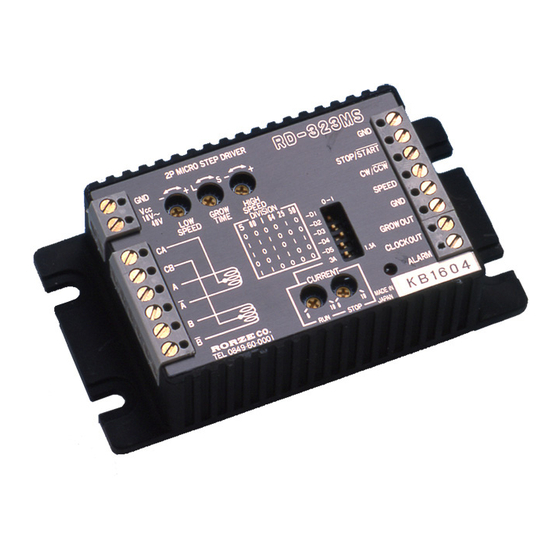
Weight Approx. 250g (8.8oz.) Outside dimensions 27.5H x 105W x 56Dmm (1.1”H x 4.1”W x 2.2”D) 4.Part Name GROW TIME Trimmer LOW SPEED Trimmer HIGH SPEED Trimmer RD-323MS 2P MICRO STEP DRIVER G N D - + L - +... -
Page 7: 5.Current Adjustment
You can set the stop current to any value between 0 and 80% of the run current by adjusting Stop Current Adjustment Trimmer. (Setting at shipment is 50 %.) Stop Current Adjustment Trimmer Graduations Fig.4. Stop Current Setting RD-323MS Arrow.com. Arrow.com. Arrow.com. -
Page 8: 6.Speed Setting
6. Speed Setting 6.Speed Setting - + S - + ☆ Adjustment of Low/High Speed Owing to the structure of the internal circuit, setting Low GROW HIGH Speed volume will affect the high speed change and vice SPEED T IME SPEED versa. -
Page 9: 7.Grow Time Trimmer
8-4 GND Use GND along with SPEED input for remote speed control. As a good practice, use a shielded wire. Refer to Fig. 10 SHIELDED WIRE SPEED 10kΩ Fig.10 Remote Speed Control RD-323MS Arrow.com. Arrow.com. Arrow.com. Arrow.com. Arrow.com. Arrow.com. Arrow.com. -
Page 10: Grow Out (Output)
8. Terminals 9. ALARM LED 8-5 GROW OUT (Output) GROW OUT output is turned ON when the motor changes from a stationary state to the speed set at High Speed trimmer. Therefore, by using the number of pulses from acceleration to GROW OUT output duration, it is possible to calculate deceleration time. -
Page 11: 10.Dip Switches
50 0 0 1 0 1 25 50 10-2 Current Range Switch (3A/1.5A) Sets the motor run current range when setting the run current adjustment trimmer to the max. value. (See Fig.3) RD-323MS Arrow.com. Arrow.com. Arrow.com. Arrow.com. Arrow.com. Arrow.com. Arrow.com. -
Page 12: 11.Timing Diagrams
11. Timing Diagrams 11.Timing Diagrams STOP/START SPEED HIGH SPEED LOW SPEED GROW OUT 0.3sec + Current down A phase current - + B phase current - Fig.13. Timing Diagram Ⅰ CLOCK OUT STOP/START CW/CCW HIGH SPEED LOW SPEED Fig.14. Timing Diagram Ⅱ T2: Changing direction of rotation from CW to CCW or vice versa should be done at least 10msec after stopping. -
Page 13: 12.Input/Output Circuits
(low level output Ic=10mA) = 0.38V (low level output Ic= 1mA) = 0.22V Fig.17. GROW OUT/CLOCK OUT/ALARM Output Circuits Do not supply the voltage more than 50V, the current more than 100mA to this terminal. RD-323MS Arrow.com. Arrow.com. Arrow.com. Arrow.com. -
Page 14: 13.Wiring Diagram
You can use any HB(hybrid) or PM(permanent magnet) stepping motor with rating of 0.3 to 3A/ph. Select motors with rating of less than supply voltage × 0.7(V). RORZE 2-Ph Stepping Motors (Torque -- 1kgf・cm = 13.9oz・in Inertia -- 1g・c㎡ = 5.46745×10 oz・in... -
Page 15: 14.Heat Dissipation
If other devices share the same power supply and voltage change can’t be allowed, then use the power supply which can flow 1.7 times of the max value of the supply current, or incorporate a large capacitor. RD-323MS Arrow.com. Arrow.com. -
Page 16: 17.Relationship Between Frequency(Pps) And Motor Speed(Rpm)
Step Angle: 1.8degree, Microstep resolution(M): 50, Frequency: 50,000pps 1.8/50×50,000×60 Motor speed(rpm)=──────────= 300 rpm 18.Dimensions 1 0 5m m (4 . 1 3" ) 9 5 mm ( 3 .7 4 ") 2P MICRO STEP DRIVER RD-323MS G N D - + L - +... -
Page 17: 19.Difference From Rd-323Ms And Rd-323M50(M10)
Stop position error described in here is the difference of the position when the driver was stopped at CW ration and CCW. This is because clock out of RD-323MS is the signal de-multiplied internal oscillation and motor is always running in microstep mode. - Page 18 Phone: +81-84-960-0001 +81-84-960-0200 Fax: E-mail address: sales@rorze.com Home page address: http://www.rorze.com *All RORZE products come with a 24-month guarantee. *Specifications and products are subject to change without any obligation on the part of the manufacturer. RCD 020201 Arrow.com. Arrow.com. Arrow.com.
Need help?
Do you have a question about the RD-323MS and is the answer not in the manual?
Questions and answers