
Related Manuals for CEL-MAR ADA-DIOC40

Summary of Contents for CEL-MAR ADA-DIOC40
- Page 1 ADA-DIOC40 User manual ADA-DIOC40 Isolated digital INPUT & OUTPUT MODBUS module io_ada-dioc40_v1.01_en Copyright © 2001-2020 CEL-MAR sp.j.
-
Page 2: Table Of Contents
ADA-DIOC40 Contents 1. GENERAL INFORMATION..................................3 1.1. WARRANTED INFORMATION..............................3 1.2. GENERAL CONDITIONS FOR SAFE USE........................... 3 1.3. CE LABEL...................................... 3 1.4. ENVIRONMENTAL PRESERVATION............................3 1.5. SERVICE AND MAINTENANCE..............................3 1.6. PACK CONTENTS..................................3 2. PRODUCT INFORMATION..................................3 2.1. PROPERTIES....................................3 2.2. -
Page 3: General Information
1.1. WARRANTED INFORMATION ADA-DIOC40 module is covered by a two year warranty from date of sale. In case of being damaged it will be repair or the damaged component will be replace. The warranty does not cover damage caused from improper use, materials consumption or any unauthorized changes. -
Page 4: Description
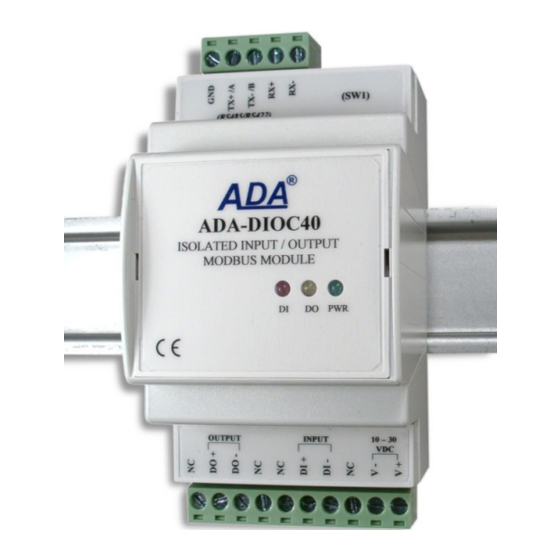
ADA-DIOC40 2.2. DESCRIPTION ADA-DIOC40 module is the executive element, that extends control systems based on RS485-MODBUS bus with the ability to read status of circuits/devices, connected to digital input, and perform controls using the digital output. ADA-DIOC40 is dedicated to working together with PLC controllers, SCADA type software and devices supports MODBUS-RTU protocol. -
Page 5: Isolation
- not supply module from power circuit device that generates large impulse interference such as transmitters, contactors. 3.1. ASSEMBLING The cover of ADA-DIOC40 module is adapted to assembly on TS-35 (DIN35) rail. To install the module, should be mounted on the rail upper part of the cover then press bottom part to hear characteristic „Click” sound. -
Page 6: Connection To Rs485/Rs422 Bus
Tx+ / A Tx-/ B Tx- / B Fig 4b. 2-Wires connection of ADA-DIOC40 to PC with the use of ADA-I9140 USB to RS485/RS422 3.3. CONNECTION TO RS485/RS422 BUS RS485/RS422 interface in ADA-DIOC40 module is described as: Tx+/A, Tx-/B, Rx+, Rx-. -
Page 7: Gnd Terminals Connection
3.4.1. CONNECTION OF QS18VP6LPQ PHOTOCELL TO DIGITAL INPUT In case of monitoring changes of the output status QS18VP6LPQ photocell, connect it to digital input of ADA-DIOC40 module like on the figure below. Additionally, the module has to be configured to communication mode “Signalling DI Status” (see section CONFIGURATION) 10 –... -
Page 8: Power Supply Connection
Power cable from DC power supplies to device can not be longer than 3m. Should connect positive (+) end of DC power supplies to V+ device terminal and negative (-) end to V- on terminal block. ADA-DIOC40 has protection against power supply reverse connection. -
Page 9: Configuration Of Addressing Mode
Fig 9. View of ADAConfig software interface 5.2.1. CONFIGURATION OF ADDRESSING MODE For ADA-DIOC40 module the addressing mode is permanently enabled, therefore should be set a proper module address from range 1 - 247. 5.2.2. CONFIGURATION OF BAUD RATE AND DATA FORMAT RS485 communication interface of module, can be set as below: a/ baud rate (kbps): 0.3, 0.6, 1.2, 1.8, 2.4, 4.8, 7.2, 9.6, 14.4, 19.2, 28.8, 38.4, 57.6, 76.8, 115.2, 230.4,... -
Page 10: Configuration Of Module Communication Mode, In The Run Mode
SW1-2 After microswitch setting, should be restarted ADA-DIOC40, by turning OFF and then ON the power supply. The yellow LED will light continuously and the module will be in Emergency Firmware Update mode. Now follow the description in the above point. -
Page 11: Diagnostics Data Transmission
For checking this counters press the button [Read transmission errors], and to delete (zeroing of counters in the memory of the module) press [Delete transmission errors]. In case of parity errors or frame errors check ADA-DIOC40 module's configuration and correctness connection of RS485 bus to RS485/422 port of the module. -
Page 12: Modbus-Rtu Communication Mode
ADA-DIOC40 0x02 – number of data bytes 0x00 – data1: current input status 0x01 – data2: previous input status 0x5A – checksum CRC16 -Low 0xFF – checksum CRC16 -Hi Checksum CRC16 is countered from first byte (0x40) to last data bytes data2 (together with this byte). -
Page 13: Function 0X02 - Readout Of Binary Input Status
ADA-DIOC40 Query Byte no. Description Size Value Module address 1 Byte 0x01 [1 to 247] Function code 1 Byte 0x01 Output address Hi 1 Byte 0x00 Output address Lo 1 Byte 0x00 Output number Hi 1 Byte 0x00 Output number Lo... -
Page 14: Function 0X03 - Readout Of Holding Registers
ADA-DIOC40 Byte no. Description Size Value CRC-Lo 1 Byte CRC-Hi 1 Byte Example. Readout of the input status 1 (address x10001 to x10001) 01-02-00-00-00-01-CRCLo-CRCHi Response Byte no. Description Size Value Module address 1 Byte 0x01 [1 to 247] Function code... -
Page 15: Function 0X05 - Change Of Single Output Status
ADA-DIOC40 Byte no. Description Size Value Data2-Hi 1 Byte 0x00 Data2-Lo 1 Byte 0x01 CRC-Lo 1 Byte CRC-Hi 1 Byte Example. Readout of output and input status (address 40001 to 40002) 01-03-04-00-01-00-01-CRCLo-CRCHi In the response, status of output 1 and input 1, are presented as 4-bytes with values: 00-01-00-01 Response - in case of error Byte no. -
Page 16: Function 0X06 - Change Of Single Holding Register Value
ADA-DIOC40 Example. Confirmation of enabling the output with the address 0 01-05-00-00-FF-00-CRCLo-CRCHi Response - in case of error Byte no. Description Size Value Module address 1 Byte 0x01 [1 to 247] Function code 1 Byte 0x85 0x01 - unknown function... -
Page 17: Crc Checksum
In this mode Signalling of DI status and Modbus – the module is working in two above modes simultaneously - this required connection 4-wire RS485 bus from the module to the master device. 7. VERSIONS ADA-DIOC40 - Version: Order example:... - Page 18 ADA-DIOC40 Protection from reverse power polarization Galvanic Isolation 1kVDC or 3kVDC between power circuit and RS-485/RS-422 – depend on version. Optoisolation ~3kV – between input&output circuits and module electronics Resistance to disruptions according to the standard PN-EN 55024. Electromagnetic compatibility Emission of disruptions according to the standard PN-EN 55022.
- Page 19 ADA-DIOC40...
- Page 20 Thank you for purchasing CEL-MAR Company products. We hope that this user manual helped connect and start up the ADA-DIOC40 module. We also wish to inform you that we are a manufacturer of the widest selections of data communications products in the world such as: data transmission converters with interface RS232, RS485, RS422, USB, Current Loop, Fibre-Optic Converters and Ethernet or Wi-Fi.
Need help?
Do you have a question about the ADA-DIOC40 and is the answer not in the manual?
Questions and answers