
Related Manuals for Sitron CF12 AC

Summary of Contents for Sitron CF12 AC
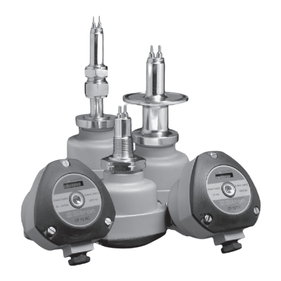
- Page 1 USER’S GUIDE Installation, Operation, Maintenance Instructions CF12 AC / CF12 DC Thermal Dispersion Flow Switch Monitor...
-
Page 2: Table Of Contents
Terms & Conditions ......... 22 www.sitron.com - email: info@sitron.com... -
Page 3: Introduction
Introduction CF12 AC / CF12 DC Thermal Dispersion Flow Switch Monitor The CF12 series of thermal flow switches is designed to monitor flow status of liquids and gases and can also be used to detect level. A chain of 8 LED's gives the user a visual indication of the flow status of the switch. There are... -
Page 4: Models & Dimensions
Process Connections ANSI 150# Tri-Clamp Connection Flange Connections Threaded Connections ANSI 300# 1” 1” ½” 1 ½” 1 ½” 3/4” TC Connection Rubber Seal 1” 2” 2” Process Connection 1 ½” 2 ½” 2 ½” 1,75 www.sitron.com - email: info@sitron.com... -
Page 5: Wiring Diagram
Wiring Diagram Nylon Enclosure (N1) CF 12 AC M12 Connector Optional Bargraph (B1) Central LED (L1) (Red/Green) NO or NC contact Adjust Connector 12mm 2000mm Adjust (P1) - Power Supply 2 - Power Supply 3 - NO Contact 4 - NC Contact 5 - Common Power Supply... - Page 6 Flow 3 - Ground CF12AC 4 - NO Contact 5 - Common 1 2 3 4 5 6 6 - NC Contact Adjust (P1) 7 - NO Contact 8 - Common 9 - NC Contact 2SPDT www.sitron.com - email: info@sitron.com...
- Page 7 Wiring Diagram (P1) - Set Point Potentiometer Adjust (B1) - 8 LED´s Bargraph: Red LED Yellow LED Green LED (L1) - Central LED - Green: With flow Red: No flow -Detect -Switch Conector M12 Adjust -Flow - Power Supply 85...260 Vac 50/60 Hz 2 - Power Supply Pin# 1/2 Power Pin# 3...
- Page 8 Wiring Diagram F12 with CF12RM Remote Controller Dimensions Bargraph Central LED(L1) Sensor - Blue Red/Green 2 - Yellow 3 - Green 4 - Red 5 - Black CF12-RM Adjust Adjust 5 A 250V ac (24Vcc) Dimensions CF12RM 44mm Sensor CF12-RM Adjust 5 A 250V ac 111mm...
-
Page 9: Cf12 Relay Status Guide
NC (6) Normal C (5) NO (4) NC (6) GREEN Alarm C (5) Application Set Point LED Status Condition CF12 SPDT Status NO (4) NC (6) GREEN Normal C (5) NO (4) NC (6) Alarm C (5) www.sitron.com - email: info@sitron.com... -
Page 10: Pre-Installation
Pre-Installation Pre-Installation Checks: Fig. 1 1) Its recommended that the flow switch is installed with a distance of ½ a meter of the pipe bent where the flow enters and 5x times the 1/2m 5xØ diameter of the pipe where the flow exits, enabling it to have an accurate reading (Fig. -
Page 11: Installation
In pipes with smaller diameters use an adaptor to enlarge the diameter of the pipe so that the sensor Fig. 5 can be properly installed (See Fig. 6). If the installation is not correct the CF12's performance may be affected. Fig. 6 www.sitron.com - email: info@sitron.com... - Page 12 Calibration To Start: 1 - Remove the enclosure lid (Note: the screws are self-retaining) 2 - Start the power supply and wait 5 minutes until the CF12 is active and has reached a stable point within the medium. 3 - Let the regular or desired flow reach its point of normal operation. Calibration for Flow / No Flow: 1 - Set the flow rate at the normal range of operation.
-
Page 13: Calibration
2 - Continue to turn potentiometer clockwise until all green LEDs in the bar graph turn on. 3 - In order to be sure that the adjustment is not at a critical state give the potentiometer an additional quarter turn clockwise. www.sitron.com - email: info@sitron.com... -
Page 14: Handling
Handling Seal the thread with Teflon tape before installation (Fig. 1). Fig. 1 Do not turn or handle by the housing (Fig. 2). Use the correct tool during installation (Fig. 3) The CF12 should not be dropped or suffer any impact or fall that could damage the electronics or the thermal tips of the probe (Fig. -
Page 15: Technical Specifications
Wetted Material 316 Stainless Steel 14 to 176º F (-10 to 80ºC) sanitary option to 248ºF (120ºC) Operating Temperature Max Pressure 1450 PSI (100 Bar) IP65 (IEC 60529) Class Protection NEMA 4X (G1 / G2 ) www.sitron.com - email: info@sitron.com... - Page 16 Technical Specifications CF12DC Flow 100 % 1 2 3 4 5 6 Adjust Ajust N1 Enclosure G1 Enclosure G2 Enclosure Flow for liquids and gas level for liquids only Application Operating Voltage 24Vdc (+/- 10%) +/- 100mA Current Consumption Relay(SPDT) 5A - 250Vac (1 SPDT G1) Output (2 SPDT - G2 or GX) aluminum enclosure Liquid: 3 cm/s to 3 m/s - Gas: 5 cm/s to 5 m/s...
- Page 17 316 Stainless Steel Wetted Material 14 to 176º F (-10 to 80ºC) Operating Temperature sanitary option to 248ºF (120ºC) Max Pressure 1450 PSI (100 Bar) Sensor: IP 65 Class Protection Controller: IP 40 www.sitron.com - email: info@sitron.com...
- Page 18 Ex proof 0539 II 2 G EX d IIC Gb / 0539 II 2 D Ex tb IIIC Db Housing Certification IECE / IECx UL 08.0005 / Ex d IIC Gb / Ex tb IIIC Db www.sitron.com - email: info@sitron.com...
-
Page 19: Ordering Information
Ordering Information MODEL CF12AC CF12DC SIZE 3/4” PROCESS CONNECTION TYPE 1” 1 1/2” 2” FLANGE ANSI 150# - Carbon Steel Painted 2 1/2” FLANGE ANSI 150# - 316 SS 3” FLANGE ANSI 150# - PVC 1 1/4” FLANGE ANSI 300# - Carbon Steel Painted FLANGE ANSI 300# - 316 SS Metric Thread... -
Page 20: Trouble Shooting
Use armored cable turns on or interference and shielded housing off suddenly Relay remains Sensor is potentialy Contact Sitron or your closed defective local representative for further instruction Montréal O ce 970 Montée de Liesse, #204 St.Laurent, QC H4T 1W7 ventes@bestobell.com...
Need help?
Do you have a question about the CF12 AC and is the answer not in the manual?
Questions and answers