
Summary of Contents for Radicom Research RB8762C Series
-
Page 1: Radicom Research, Inc
Radicom Research, Inc. Designer’s Guide for RB8762C Series (RoHS BLE 5.1 Serial Bluetooth Modules) Compliant SIG DID: D057234 Date: 03/14/2019 Doc#RRD2Z50-20190314001-A09-C2... -
Page 2: Table Of Contents
Research assumes no responsibility for its use, or any infringement of patents or other rights of third parties that may result from its use. Radicom Research reserves the right to change circuitry at any time without notice. This document is subject to change without notice. - Page 3 Introduction Thank you for choosing Radicom RB8762C Module. We are committed to providing you quality service and technical support. The RB8762C modules are designed to meet OEM’s needs of embedding low power, wireless data connectivity to their products. The RB8762C family offers a quick and simple solution for wireless Bluetooth communications.
-
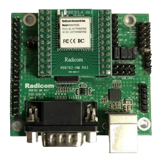
Page 4: Rb8762C Evk And Ble Functionality
RB8762C EVK and BLE Functionality Radicom provides RB8762C-EVK (development kits) as a quick platform for testing and evaluating the RB8762C and RB8762CHM Bluetooth modules. The kit includes two RB8762C modules mounted on the RB8762CHM DIP Module. Each RB8762CHM is installed into a RB8762CMB evaluation board. -
Page 5: Features
Features Support the Bluetooth 5.1 core specification Frequency Range 2.402 – 2.480 GHz Integrate MCU to execute Bluetooth protocol stack Ultra low power consumption with intelligent PMU Supports Master and Slave modes Support fully multiple Low Energy states ... -
Page 6: Approvals
Approvals FCC Certification 47 CFR FCC Part 15.247 & ANSI C63.10 2013 KDB 558074 D01 v03r05 FCC 1.1310 CE Certification EN 300 328 V2.1.1 ETSI EN 301 489‐17 V2.2.1 / ETSI EN 301 489‐1 V1.9.2 EN 61000‐3‐2: 2014 / EN 61000‐3‐3: 2013 ... -
Page 7: Model Naming System
Model Naming System Product Series: RB8762C- (x) - (x) Optional a: on-board antenna c: IPEX connector Optional G: with G sensor Blank: without G sensor FCC/CE certified: RB8762C-(a/c)-G RB8762C-(a/c) IC certified: RB8762C RB8762CJF Designer’s Guide (RRD2Z50‐20190314001‐A09‐C2) ... -
Page 8: Rb8762C Module Mechanical Dimensions & Pin Definitions
RB8762C Module Mechanical Dimensions & Pin Definitions Top View Unit: mm[inch] Size: Module= 17.5 x 15.0 x 2.75 mm [0.69” x 0.59” x 0.11”] Side View Front View Pin Definitions RB8762CJF Designer’s Guide (RRD2Z50‐20190314001‐A09‐C2) ... -
Page 9: Rb8762Chm Mechanical Dimensions & Pin Definitions
RB8762CHM Mechanical Dimensions & Pin Definitions Size: RB8762CHM(w/o pin header)= 30.6 x 28 x 5.6 mm [1.2” x 1.1” x 0.24”] Pin header pitch = 6mm [0.2”] Unit: mm[inch] Top View Side View Front View Pin Definition RB8762CJF Designer’s Guide (RRD2Z50‐20190314001‐A09‐C2) ... -
Page 10: Rb8762Cmb Mechanical Dimensions
RB8762CMB Mechanical Dimensions Size: Evaluation Board= 62.6 x 55.1 x 15.0 mm [2.5” x 2.2” x 0.6”] Unit: mm[inch] Top View 2-PH 2.54_2X11P;H=8.4 2-PH 0.10_2X11P;H=0.33” Side View Front View RB8762CJF Designer’s Guide (RRD2Z50‐20190314001‐A09‐C2) ... -
Page 11: Rb8762Cmb Rs232 Db9 Pin Definitions
RB8762CMB RS232 DB9 Pin Definitions The pin definitions of DB9 used on the RB8762CMB RS232 Serial Connector are as follows: Pin Signal name DCD (Input, Carrier Detect) RXD (Input, Received Data) TXD (Output, Transmit Data) DTR (Output, Data Terminal Ready) GND (Ground) DSR (Input, Data Set Ready) RTS (Output, Request to Send) -
Page 12: Layout Design Suggestions
Layout Design Suggestions General Layout Rules: All Printed Circuit Boards must comply with UL94V0 standard for flammability. Always use RoHS compliant Parts and materials. Suggestions for Layout: Step 1. Do not place Power circuit, X’tal, Inductor, etc. near RF area. Step 2. -
Page 13: Rb8762C Evk Development Board Figure And Functions
RB8762C EVK Development Board Figure and Functions The RB8762CMB Development Board has white silkscreen legend located by the switches and connectors described below. 1. RS232 male DB-9 connector (J32) 2. Rows keys (J14) Row 0 > P1_2 , Row 1 > P1_3 , Row 2 > P1_4 , Row 3 > P1_5 Row 4 >... - Page 14 5. UART interface header (J3) 6. GPIO interface header (J2) 7. RS232 _ UART header (J17) 8. I2C interface header (J8) 9. USB_UART header (J13) 10. SPI interface header (J4) 11. Power LED indicator 12. USB 5V slot (U3) RB8762CJF Designer’s Guide (RRD2Z50‐20190314001‐A09‐C2) ...
-
Page 15: Operating Rb8762C Mb
Operating RB8762C MB Introduction: Radicom provides RB8762CMB Development Kit as a quick platform for testing and evaluating the RB8762CHM Bluetooth module. Each RB8762CMB has an UART and USB connector interface. You may choose either UART or USB interface for data transmission. If you use UART interface to transmit your data, please plug one null cable to COM port and insert a 4 pieces jumper into J17 (as below). - Page 16 Hardware Set-up - To provide power to the RB8762CMB, plug one end of the USB cable into USB connector on the RB8762CMB. Plug the other end into the PC USB port. PC Set-up - Turn on the PC. To send the AT commands and transmit & receive data with the RB8762CMB use a serial communication package such as Docklight.
- Page 17 Step 3. After these steps, power on the RB8762CMB and you’ll see device information as below. ※Actual version of RB8762CMB and BT device address might be different as above. If you want to know the latest FW version, please contact Radicom. RB8762CJF Designer’s Guide (RRD2Z50‐20190314001‐A09‐C2) ...
-
Page 18: Supported At Command List
Supported AT Command List AT Commands Slave Side Master Side Description √ √ Test UART channel at+laddr √ √ Read BD address at+name √ √ Read device name Set device name(Max. length=16 byte) Default name is “Radicom”. at+name<Parameter> √ √ After changing name, you should use “at+reset\r\n”... - Page 19 AT Commands Slave Side Master Side Description Stop searching for BT device. *Must-do at+sinq Invalid √ step, or master device will keep searching. Connect a slave device. at+conn< Parameter> Invalid √ *Input parameter from “AT+INQ”. Check role, FW version, device name and at+i √...
-
Page 20: At-Command In Docklight
AT-Command in Docklight Master EVB Slave EVB Step 1. Enter “at+role=1<CR><LF>” to set as master. Step 2. Enter “at+role=0<CR><LF>” to set as slave. Step 3. Enter “at+name<CR><LF>” to read device name. +Name=Radicom Step 4. Enter “at+laddr<CR><LF>” to read BD address. +LADDR=0012A1123456 Step 5. - Page 21 Firmware behavior: The current newest version is V08 and its major different with old versions are: 1. Booting When RB8762C is booting, its role (slave or master) will depend on the setting value. This value can be got by AT command “at+role\r\n” and the factory default value is “2”. 1.1 If the value is “0”, RB8762C will work as a slave.
-
Page 22: Ota Upgrade Firmware
OTA Upgrade Firmware This chapter will show you how to use OTA to upgrade firmware. If the version of target device is larger than V07, please refer section 2. Section 1 Step 1. Plug in USB cable to power on RB8762CMB. Step 2. - Page 23 Step 6. Launch OTA APP and search for “Radicom_OTA” device. Then click the device to enter next step. Step 7. Click “Select File” from APP. Click “UPLOAD”. RB8762CJF Designer’s Guide (RRD2Z50‐20190314001‐A09‐C2) ...
- Page 24 Step 8. The firmware upgrade will start immediately. Once the screen shows “Update Success!” means firmware upgrade successfully. Step 9. When new firmware upgraded successfully through OTA, you must return RB8762CMB to its original mode (master/slave). Issue “at+role0<CR><LF>” to enter slave mode and “at+role1<CR><LF>”...
- Page 25 Section 2 Step 1. Install OTA APP in your smart phone and execute APP. Step 2. Plug in USB cable to power on RB8762CMB. Step 3. After 10 second, APP will scan BT device name. Then click to connect. Step 4. “Select File” Radicom released image to upgrade the slave device then click “UPLOAD” Step 5.
-
Page 26: How To Access Rb8762C From Smartphone
How to access RB8762C from smartphone The RB8762C can support two mainly platform for smartphone (iOS and Android). You can access RB8762C from smartphone by 3rd app or your own designed app. Here we provide some notes for access RB8762C from smartphone, also some examples. ※This chapter assumes that the reader has a basic understanding of the BLE specification including some knowledge of service, characteristic and transfer protocols. - Page 27 Customed APP If you want to build your own BLE APP, please refer to below official documents and examples. Android Documentation https://developer.android.com/guide/topics/connectivity/bluetooth-le.html Example https://github.com/googlesamples/android-BluetoothLeGatt/#readme Documentation https://developer.apple.com/library/content/documentation/NetworkingInternetWeb/Conceptual/Co reBluetooth_concepts/CoreBluetoothOverview/CoreBluetoothOverview.html#//apple_ref/doc/uid/ TP40013257-CH2-SW1 Example https://developer.apple.com/library/content/samplecode/BTLE_Transfer/BTLE_Transfer.zip RB8762CJF Designer’s Guide (RRD2Z50‐20190314001‐A09‐C2) ...
-
Page 28: The Wired Method Upgrades Rb8762C Firmware Code
The wired method upgrades RB8762C firmware code 1. Software platform and software Windows 7 Service Pack 1, BeeMPTool2.0.5, App image: APP_1.1.11894.12638-0d68345b87439211a079cb98bb0 (The app image will change for each release.) 2. Hardware type: 3. Pin Definitions RB8762CJF Designer’s Guide (RRD2Z50‐20190314001‐A09‐C2) ... - Page 29 3.1 Wired Connection We will use RB8762CMB to update firmware. In order to do that, we need connect these 5 wires form RB8762C module to RB8762CMB. RB8762CMB is RB8762CEVK without the RB8762CHM Below is the picture of our sample with 5 wires connected. RB8762CJF Designer’s Guide (RRD2Z50‐20190314001‐A09‐C2) ...
- Page 30 If your 8762C already soldered in your board and VDD_3V3 provided, please do not connect VDD_3V3. You only need 4 wires (3 signals and Ground) The following procedures can be verified from RB8762CEVK (RB8762CMB + RB8762CHM). The difference is using RB8762CHM into RB8762CMB and the other is Using RB8762C module wired into RB8762CMB.
- Page 31 4.1.3 Operating Steps: a. P3_0 jumper ON b. Power ON c. Wait for at least 15 seconds d. Burn Image (Steps 4.1.4 to step 9) e. Power OFF P3_0 Jumper OFF g. Use Cell phone (Android or iOS) to check Bluetooth device. You can verify the Bluetooth address to identify newly update.
- Page 32 Step 5: After Click on Set Config file, you can set your BT address of new firmware. You can check BT address after successfully update the firmware (from cellular phone) Step 6: Confirm then close this window Step7: Select "Patch Image" and “APP Image” Step8: Download successfully Step9: Finished and close this window.
- Page 33 Power off RB8762C EVK then power on. The RB8762CEVK will be with the new image. Summary of operating Steps: a. P3_0 jumper ON b. Power ON c. Wait for at least 15 seconds to erase firmware. d. Burn Image (Steps 4.1.4 to Step 9) e.
-
Page 34: Fcc , Ic, Ncc Label And Model Identification
FCC , IC, NCC Label and Model Identification The RB8762C module family is FCC Part 15 and IC (Industry Canada) certified. The RB8762C is a lso CE marked. The modules are labeled with the RB8762C module model number and FCC Part 15 ID, IC registration number and CE mark. - Page 35 peripheral requirements, etc). IMPORTANT NOTE: In the event that this condition cannot be met then the FCC authorization is no longer considered valid and the FCC ID cannot be used on the final product. In these circumstances, the OEM integrator will be responsible for re-evaluating the end product (including the transmitter) and obtaining a separate FCC authorization.
- Page 36 Host (End Product) Labeling Requirements To maintain compliance, the end product hosting the module must be properly labeled to identify that this module is installed. The final end product must have a label located in a visible area with the following information: XXXXXXX is for the model of the module used in the end equipment.
- Page 37 FCC RF Radiation Exposure Statement IMPORTANT NOTE: To comply with the FCC RF exposure compliance requirements, this device must not be co-located or operating in conjunction with any antenna or transmitter. This device contains a low power transmitter. When this device is operational, use only with the supplied, or recommended antenna.
- Page 38 pas produire de brouillage, et (2) l’utilisateur de l’appareil doit acceptor tout brouillage radioelectrique subi, meme si le brouillage est susceptible d’en compromettre le fonctionnement. NCC: 取得審驗證明之低功率射頻器材,非經核准,公司、商號或使用者均不得擅自變更頻 率、加大功率或變更原設計之特性及功能。低功率射頻器材之使用不得影響飛航安全 及干擾合法通信;經發現有干擾現象時,應立即停用,並改善至無干擾時方得繼續使 用。前述合法通信,指依電信管理法規定作業之無線電通信。低功率射頻器材須忍受 合法通信或工業、科學及醫療用電波輻射性電機設備之干擾。 安裝該模組之主體裝置或設備上必須標示『內含發射器 模組: FCC: RF exposure warning This equipment must be installed and operated in accordance with provided instructions and the antenna(s) used for this transmitter must be installed to provide a separation distance of at least 20 cm from all persons and must not be co‐located or operating in conjunction with any other antenna or transmitter. End‐users and operating conditions for installers must be provide with antenna installation instructions and transmitter ...
- Page 39 This device has also been evaluated and shown compliant with the IC RF Exposure limits under mobile exposure conditions. (antennas are greater than 20cm from a person's body). Informations concernant l'exposition aux fréquences radio (RF) La puissance de sortie émise par l’appareil de sans fil est inférieure à la limite d'exposition aux fréquences radio d'Industry Canada (IC). Utilisez l’appareil de sans fil de façon à minimiser les contacts humains lors du fonctionnement normal. Ce périphérique a également été évalué et démontré conforme aux limites d'exposition aux RF d'IC dans des conditions d'exposition à des appareils mobiles (antennes sont supérieures à 20 cm à partir du corps d'une personne). This radio transmitter IC: 2377A-RB8762C has been approved by Innovation, Science and Economic Development Canada to operate with the antenna types listed below, with the maximum permissible gain indicated. Antenna types not included in this list that have a gain greater than the maximum gain indicated for any type listed are ...
-
Page 40: Ce Declaration Of Conformity
Europe – R&TTE Compliance Statement: Hereby, Radicom Research Inc. declares that this equipment complies with the essential requirements and other relevant provisions of LVD 2014/53/EU and EMC 2014/30/EU OF THE EUROPEAN PARLIAMENT AND THE COUNCIL of April 14, 2014 on Radio Equipment Directive (RED) 2014/53/EU and the mutual recognition of their conformity. -
Page 41: Limited Warranty
Limited Warranty Warranty Coverage and Duration Radicom Research, Inc. (“RRI”) warrants to the original purchaser its RRI-manufactured products (“Product”) against defects in material and workmanship under normal use and service for a period of one year from the date of delivery. During the applicable warranty period, at no charge, RRI will, at its option, either repair, replace or refund the purchase price of this Product, provided it is returned in accordance with the terms of this warranty to RRI. - Page 42 What this Warranty does NOT Cover: Defects or damage resulting from use of the Product in other than its normal and customary manner. Defects or damage from misuse, accident or neglect. Defects of damage from improper testing, operation, maintenance, installation, alteration, modification or adjustment.
-
Page 43: Contacting Radicom Research
Contacting Radicom Research If more information or technical support is needed, please contact us: 671 E Brokaw Road San Jose, CA. 95112 USA Telephone: (408) 383 9006 Fax: (408) 383 9007 Mail: sales@radi.com http://www.radi.com/ RB8762CJF Designer’s Guide (RRD2Z50‐20190314001‐A09‐C2) ...
Need help?
Do you have a question about the RB8762C Series and is the answer not in the manual?
Questions and answers