
Summary of Contents for BSM Webex 840
- Page 1 All manuals and user guides at all-guides.com AR3399RK Quick Start Guide Ver 0.1 This Quick Start Guide is for BCM AR3399RK ARM motherboards based on Rockchip RK3399 Cortex A72+A53 platform.
- Page 2 All manuals and user guides at all-guides.com Contents Overview…………………………………………………….3 Mainboard Illustration…………………………………….4 Getting Started……………………………………………..5 Jumper and Connector pin out………………………….7 AR3399RK Quick Start Guide Page 2...
- Page 3 All manuals and user guides at all-guides.com 1. Overview AR3399RK Rockchip® RK3399 Dual Core Cortex-A72 + Quad Core Cortex-A53 (6-Core) SoC ARM Motherboard • Rockchip® RK3399 Dual Core Cortex-A72 + Quad Core Cortex-A53 (6-Core) SoC • 2GB DDR3L Onboard (Expandable to 4GB Max) •...
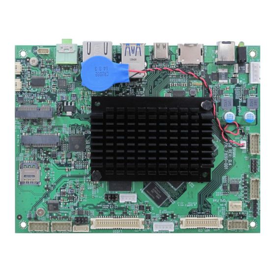
- Page 4 All manuals and user guides at all-guides.com 2. Board IO/Jumper illustration Board Top view: AR3399RK Quick Start Guide Page 4...
- Page 5 All manuals and user guides at all-guides.com 3. Getting started 1. Insert a bootable uSD card into slot CN23 if booting from uSD instead of eMMC. Note: do not force the card into the slot; it should go in with moderate pressure 2.
- Page 6 All manuals and user guides at all-guides.com 4. if you need console access, connect a serial (TTL) to USB adapter from CN11 to your workstation. Set your terminal settings to the following: 115200 bps, 8bits, no parity, 1 stop bit, and no flow control 5.
- Page 7 All manuals and user guides at all-guides.com 4. Jumper Settings and Pin Definition Boot Mode Front Panel Connector type:HDR 1x2 2.0mm Connector type:HDR 2x4 2.0mm DIP Definition Definition Definition PMIC_PWRON VCC_RTC Default RK808D_RESET BOOT MODES Usage Open Normal Boot Effect Close Recovery Mode Short pin 7-8...
- Page 8 All manuals and user guides at all-guides.com CH7511 LVDS FW mode LINE OUT Connector type:HDR 2x4 2.0mm DIP Connector type:3.5mm Phone Jack Green Definition Definition Definition 9904_SPC 9904_SPD AD_AGND SPC1 SPD1 LOUT_R 9904_SPC 9904_SPD L-DET EE100_SPC EE100_SPD AD_AGND Default LOUT_L Jumper selector 9904 EEPROM 1-2, 5-6...
- Page 9 All manuals and user guides at all-guides.com DC JACK Connector type:DC-JACK 6.5/2.5mm Connector type:RTA-164AAK1A Definition Definition Definition 12V DC-IN GE_MDI0+ GE_MDI3+ GE_MDI0- GE_MDI3- GE_MDI1+ LED2 GE_MDI1- D3V3 D3V3 LED1 GE_MDI2+ GE_MDI2- CN7 : USB3.0x2 (Type A) Connector type:UEA11123-8HD1-4H AR3399RK Quick Start Guide Page 9...
-
Page 10: Nano Sim Card
All manuals and user guides at all-guides.com SPK OUT R SPK OUT L Connector type:Header 1X2 1.25 Connector type:Header 1X2 1.25 Definition Definition SPK_R_OUT+ SPK_L_OUT+ SPK_R_OUT- SPK_L_OUT- CN10 M.2 Key E Slot CN11 UART Debug Console Connector type:Header 1X4 2.54 Standard M.2 Key E pinout Definition VCC3V3... - Page 11 All manuals and user guides at all-guides.com CN16 CPU FAN CN17 Connector type:HDR 1x3 2.54mm Wafer Connector type:HDR 2x5 2.0mm DIP Definition Definition Definition VCC3V3 VCC5V EXT_I2C_SCL EXT_I2C_SDA I2C_SCL_5V I2C_SDA_5V CN19 : LVDS0 Connector type:HIROSE DF13A-40DP-1.25 Definition Definition Definition LVDS_3.3V LVDS_DB1- LVDS_DA1+ LVDS_5V...
- Page 12 All manuals and user guides at all-guides.com CN20:I2C Touch Panel CN21:Digital IO Connector type:HDR 1x6 1.25mm Connector type:Header 2X5 2.0mm Definition Definition Definition LVDS_TH_RST# DIO0 DIO5 LVDS_TH_SCL VCC3V3 DIO3 LVDS_TH_SDA DIO1 DIO6 CAP_TCH_INT0 DIO4 DIO2 DIO7 VCC3V3 CN22:USB2.0 1/2 CN23:Micro SD Card Socket Connector type:Header 2X5 2.0mm Connector type:112A-TAAR-R02 Definition...
- Page 13 All manuals and user guides at all-guides.com CN26:9904 EEPROM Update Header CN27:External 12V Output Connector type:HDR Wafer 1x4 2.0mm Connector type:HDR Wafer 1x4 2.5mm Definition Definition DC_IN_C EE100_SPC DC_IN_C EE100_SPD AR3399RK Quick Start Guide Page 13...
Need help?
Do you have a question about the Webex 840 and is the answer not in the manual?
Questions and answers