Table of Contents
Advertisement
Available languages
Available languages
Quick Links
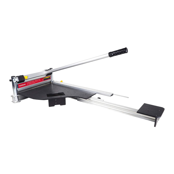
13" INDUSTRIAL SIDING + LAMINATE CUTTER
WITH SLIDING TABLE EXTENSION
OWNERS MANUAL
REVETREMENT EXTÉRIEUR INDUSTRIEL
JUSQU'À 13" + COUPE DE STRATIFIÉE
AVEC TABLE EXTENSIONS COULISSANTE
MANUEL D'UTILISATION
WARNING
Read and understand all instructions. Failure to follow all instructions may result in serious bodily injury.
SAVE THESE INSTRUCTIONS FOR FUTURE REFERENCE.
AVERTISSEMENT
Lire et comprendre toutes les directives. Le non-respect des directives peut causer des blessures graves.
VEUILLEZ CONSERVER CES DIRECTIVES POUR RÉFÉRENCE ULTÉRIEURE.
Advertisement
Table of Contents

Related Manuals for NORSKE NMAP004

Summary of Contents for NORSKE NMAP004
- Page 1 13” INDUSTRIAL SIDING + LAMINATE CUTTER WITH SLIDING TABLE EXTENSION OWNERS MANUAL REVETREMENT EXTÉRIEUR INDUSTRIEL JUSQU’À 13” + COUPE DE STRATIFIÉE AVEC TABLE EXTENSIONS COULISSANTE MANUEL D’UTILISATION WARNING Read and understand all instructions. Failure to follow all instructions may result in serious bodily injury. SAVE THESE INSTRUCTIONS FOR FUTURE REFERENCE.
-
Page 2: Safety Rules
WARNING VERY SHARP BLADE WARNING! FAILURE TO FOLLOW THESE RULES MAY RESULT IN SERIOUS INJURY! USING THIS MACHINE WITH RESPECT AND CAUTION WILL CONSIDERABLY LESSEN THE POSSIBILITY OF PERSONAL INJURY. SAFETY RULES READ AND UNDERSTAND THIS MANUAL BEFORE OPERATING 1. If you are not thoroughly familiar with the operation of the 13” cutter, obtain advice from a qualified instructor. - Page 3 SET UP ASSEMBLY Assemble the table assembly (Fig. 1-A) Fig.1 to the blade assembly (Fig. 1-B) using 4 small Phillips head screws (Fig. 1-C) to secure the top of the table. Use two larger pan head screws (Fig.1-D) to secure the table brace.
- Page 4 CUTTING CUTTING Insert material between the cutting blade and the base, flush with the aluminum fence (Fig. 4-A) and hold the material with foot then push handle down to complete a cut. WARNING! Maintain control of the handle. Do not allow handle to slam back after making cut.
- Page 5 CUTTING ADJUSTING THE TABLE EXTENSION The laminate flooring cutter is equipped with a sliding extension table (Fig. 7-A) for supporting longer boards (41” working length). To adjust, loosen knob (Fig. 7-B) and extend table to desired length then tighten knob to lock in place. Insert material between the cutting blade and the base, flush with the aluminum fence;...
-
Page 6: Blade Adjustment
BLADE ADJUSTMENT ADJUSTING THE BLADE 1. Unscrew and remove the adjustment plate screws (Fig. 8). 2. Tighten both adjustment plates by 1 or 2 holes (Fig. 9). NOTE: The pitch on each lifting screw is .125mm. The adjustment on both plates must be the same. -
Page 7: Maintenance
100+ cuts and when the blade has been re-sharpened. With the blade (Fig. 10-B) installed and positioned roughly 1/8” above the table top, NORSKE lay the flat side of your honing stone HONING STONE: (Fig. 10-A) against the flat side of the blade. - Page 8 EXPLODED PARTS DIAGRAM WARNING VERY SHARP BLADE - 8 -...
-
Page 9: Parts List
PARTS LIST PART# DESCRIPTION Plastic end cap Cap screw (M10x70x32.5) Guide sleeve Left Guide sleeve Right Camshaft Round hd allen screw (M6x16) Stop knob (M6x17) Stop block Round hd allen screw (M6x12) 13” HSS knife (340x28x2) Pan hd screw (M6x40) Countersunk screw (M5x20) Ruler Guiding rod... -
Page 10: Règles De Sécurité
AVERTISSEMENT LAME TRÈS TRANCHANTE ATTENTION! LE NON-RESPECT DE CES RÈGLES POURRAIT ENTRAÎNER DE GRAVES BLESSURES! UTILISER CET OUTIL AVEC ATTENTION ET PRUDENCE DIMINUERA CONSIDÉRABLEMENT LES POSSIBILITÉS DE BLESSURES CORPORELLES RÈGLES DE SÉCURITÉ LISEZ ET COMPRENEZ BIEN LE MANUEL D’UTILISATION AVANT D’UTILISER LA CISAILLE DE 330MM Si vous n’êtes pas familier avec le fonctionnement du couteau à... - Page 11 ASSEMBLAGE ASSEMBLAGE Assemblez la table. (Fig. 1-A) au châssis de coupe (Fig. 1-B). Pour fixer le haut de la table, utilisez quatre petite vis à tête Phillips (Fig. 1-C). Pour fixer le support de la table, utilisez deux vis à tête bombée (Fig.
- Page 12 COUPE COUPE Insérer le matériau entre la lame de coupe et la base, en s’appuyant sur la bordure d’aluminium (Fig. 4-A) et maintenez le matériau en place puis poussez la poignée pour terminer la coupe. RÉPÉTITION DES COUPES Le couteau de sol stratifié est équipé d’une jauge de mesure réglable (Fig.
- Page 13 COUPE AJUSTER LA RALLONGE DE LA TABLE Le couteau à plancher pour stratifier est équipé avec une rallonge coulissante (Fig. 7-A) pour supporter des planches plus longues (41 po longueur de travail). Pour ajuster, desserrer le bouton (Fig. 7-B) et étendre la table à...
- Page 14 AJUSTEMENT DE LA LAME AJUSTEMENT DE LA LAME 1. Dévisser et retirer les vis de la plaque d’ajustement (Fig. 8). 2. Resserrer les deux plaques d’ajustement d’un ou deux trous (Fig. 9). NOTA: Le pas de chaque vis est de .125 mm. L’ajustement des deux plaques doit être le même.
-
Page 15: Entretien
ENTRETIEN AFFILER LE COUTEAU Il est très important d’enlever les bavures du bord à plât du couteau. L’affilage d’un nouveau couteau devrait être fait après les 40 à 100 premières coupes, après chaque 100+ coupes et lorsque le couteau a été ré-aiguisé. Avec le couteau (Fig. - Page 16 DIAGRAMME DES PIÈCES AVERTISSEMENT LAME TRÈS TRANCHANTE - 16 -...
-
Page 17: Liste Des Pièces
LISTE DES PIÈCES DESCRIPTION QTÉ. Capuchon en plastique Boulon à tête cylindrique (M10x70x32.5) Manchon de guide (Gauche) Manchon de guide (Droit) Galet Arbre à came Vis à tête ronde “Allen” (M6x16) Bouton d’arrêt (M6x17) Bloc d’arrêt Vis à tête ronde “Allen” (M6x12) Couteau AHV de 330 mm (340x28x2) Vis à... - Page 18 NOTES noteS / noteS / notaS - 22 - - 18 -...
- Page 19 NOTES noteS / noteS / notaS - 22 - - 19 -...
- Page 20 Made in China Fabriqué en Chine Fabricado en China NORSKE TOOLS LTD Vancouver, BC www.norsketools.com...
Need help?
Do you have a question about the NMAP004 and is the answer not in the manual?
Questions and answers