
Related Manuals for Richard Wolf ENDOCAM 552510 Series

Summary of Contents for Richard Wolf ENDOCAM 552510 Series
- Page 1 Instruction Manual Logic HD Camera Controller ENDOCAM 552510x Logic 4K Camera Controller ENDOCAM 5525301 GA-A282 / 2018-04 V10.0 / PK17-9038...
- Page 2 +32 92 82 92 16 france@richard-wolf.com austria@richard-wolf.com endoscopy@richard-wolf.be www.richard-wolf.com www.richard-wolf.be Marketing Office INDIA U.A.E RICHARD WOLF India Private Ltd. RICHARD WOLF Middle East JMD Pacific Square P.O. Box 500283 No. 211 A, Second Floor AL Thuraya Tower 1 Behind 32 Milestone Floor,...
-
Page 3: Table Of Contents
Contents General information ............Symbols . - Page 4 5.4.1 Overview - menu structure - "operation" main menu ......5.4.2 Overview - menu structure - "Settings" main menu .
- Page 5 Contents 8.2.1 Camera controller extension options ......... . 8.2.2 Input interfaces .
-
Page 6: General Information
General information Symbols Designation Symbols Attention, Caution Follow the instruction manual OFF (no power supply, separation from mains) On (power: connection to the power/mains) Equipotentality Fuse Alternating current (AC) μ TYPE CF APPLIED PART Camera head connector USB interface Data input Data output Network, LAN (Ethernet) interface Manufacturer... -
Page 7: Symbols On Handheld Remote Control (Option)
Designation Symbols A Registered Trademark of a Recognized Testing Laboratory, confirm the compliance to the standard of Medical Electrical Equipment CAN/CSA C22.2 No.60601-1 (c) and ANSI/AAMI ES60601-1 (us) Identification in conformity with medical devices directive 93/42/EEC only valid if the product and/or packaging is marked with this symbol. -
Page 8: Intended Use
Intended use The products Logic HD Camera Controller 552510x and Logic 4K Cam era Controller 5525301 are used for visualizing natural or artificially cre ated hollow spaces through images generated by a rigid or flexible endo scope via natural or surgically created passages within the scope of diagnostic or therapeutic medical endoscopy. -
Page 9: Contraindications And Side Effects
Contraindications and side effects 1.5.1 Contraindications Contraindications directly related to the product are presently unknown. On the basis of the patient's general condition the doctor in charge must decide whether the planned use is possible or not. For further notes and instructions please refer to the latest medical litera ture. -
Page 10: Combinations
For operation in blue light mode please observe instruction manual GA- A324 for the blue system. IMPORTANT! Connect only USB accessories tested and approved by Richard Wolf to the USB interfaces. Otherwise interference or malfunction cannot be ex cluded. IMPORTANT! -
Page 11: Equipotentality
1.7.1 Equipotentality The potential equalization cable represents a direct connection between a medical electrical device and a potential equlization rail. It serves to equalize differences in potential between enclosures of elec trical equipment and firmly installed conductive parts in the patient envi ronment. -
Page 12: Requirements For The Products / Components Of A Combination
When connected via the same multiple socket strip under standard conditions, the earth leakage current of the socket strip must not exceed 5 mA. e.g. Richard Wolf video cart with "isolating transformer" Only connect devices with a safety extra-low voltage of no more than 60 V DC / 42.4 V AC peak to the connectors for electrical connections, i.e. the signal inputs and outputs. -
Page 13: Electromagnetic Compatibility (Emc) - Iec 60601-1-2 : 2007
IMPORTANT! Persons combining products to form a system are responsible for not impairing the system's compliance with perfor mance and safety requirements, and that the technical data and the intended use are adequately fulfilled. Possible electromagnetic or other interference that may occur between the product and other products can cause faults or malfunctions. - Page 14 Guidelines and manufacturer's declaration - Electromagnetic immunity for products that are not life-supporting The product is intended for use in the environment specified below. The user must assure that the product is used in such an environment. Immunity tests IEC 60601 test level Compliance Electromagnetic environment - Guidelines Portable and mobile RF communications equipment should...
-
Page 15: Electromagnetic Compatibility (Emc) - Iec 60601-1-2 : 2014
Electromagnetic compatibility (EMC) - IEC 60601-1-2 : 2014 Please observe the following: The device/system, in the following referred to as product, always relates to Logic HD Camera Controller 552510x and Logic 4K Camera Controller 5525301. Guidelines and manufacturer's declaration - Electromagnetic emissions The product is intended for use in the environment specified below. - Page 16 Guidelines and manufacturer's declaration - Electromagnetic immunity for products that are not life-supporting The product is intended for use in the environment specified below. The user must assure that the product is used in such an environment. Immunity tests IEC 60601 test level Compliance Electromagnetic environment - Guidelines Portable and mobile RF communications equipment should...
-
Page 17: Connection Diagram - Camera Controller In Video Mode
1.10 Connection diagram - Camera Controller in video mode Legend Direct connection core LAN (Ethernet) connection cable (option) - nova System Video cables in accordance with the signal types of the Camera Controller used Connection via recording devices Video cables in accordance with signal types of the Camera Controller and recording devices used IMPORTANT! Connection of the LAN (Ethernet) connection cable (1) only in the case of an interactive light source. -
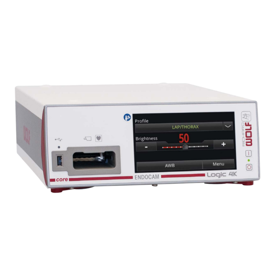
Page 18: Illustration
Illustration Front view - Camera Controller for all models Legend Power/mains switch Camera socket (type CF applied part) Power ON/OFF LED USB 2.0 interface (for external storage media) Touch-screen GA-A282... -
Page 19: Rear View - Logic Hd Camera Controller 552510X
Rear view - Logic HD Camera Controller 552510x REMOTE VIDEO DC OUT HD- SDI 3G- SDI 3G- SDI S- VIDEO HDMI FEDERAL LAW RESTRICTS THIS UNIT TO BE USED OR SOLD, EXCEPT UNDER THE SUPER- VISION OF A MEDICAL DOCTOR. Legend HDMI HD output Power supply 5V DC, 12V DC... -
Page 20: Rear View - Logic 4K Camera Controller 5525301
Rear view - Logic 4K Camera Controller 5525301 REMOTE DC OUT HDMI HD- SDI 3G- SDI 3G- SDI HDMI FEDERAL LAW RESTRICTS THIS UNIT TO BE USED OR SOLD, EXCEPT UNDER THE SUPER- VISION OF A MEDICAL DOCTOR. Legend HDMI HD output Power supply 5V DC, 12V DC USB 2.0 port Remote output connectors... -
Page 21: Illustration Of Handheld Remote Control Unit (Option)
Illustration of handheld remote control unit (option) 20.1 20.4 20.2 20.3 20.5 Legend Handheld control unit (option) 20.3 Function keys I and II (programmable key assignment) 20.1 OK button for confirmation 20.4 ESCAPE button - back 20.2 Cursor keys 20.5 USB port GA-A282... -
Page 22: Setup
Setup WARNING! The device is not protected against explosions. Explosion hazard. Do not operate this device in areas where there is a danger of explosion. WARNING! Danger if a power supply without protective earth is used. Danger of electric shock! Connect the device only to a power supply with protective earth connec... - Page 23 CAUTION! The device may fail due to overheating. In the case of insufficient air supply, a warning is issued. There is no au tomatic over-temperature cut-out. Units with a cooling device [e.g. fan] require a minimum distance of 15 cm from the wall and unobstructed vent slots.
-
Page 24: Connection To The Core Nova System
core Connection to the nova system IMPORTANT! The plug of the LAN (ethernet) connection cable must engage in the LAN (Ethernet) network socket of the device. Use only LAN (Ethernet) connection cables with the corresponding lock ing tab on the plug. IMPORTANT! After connection to the core nova system, carry out a function check with the connected devices. -
Page 25: Selecting The Menu Language
IMPORTANT! Never pull at the camera cable. Never squeeze, pinch and/or excessively bend the camera cable as this may cause damage to the wiring resulting in image failure. Fig. 1 Legend Compatible camera head Endoscope RIWO Light cables Selecting the menu language During the initial setup, set the menu language in the "Settings - Menu settings"... -
Page 26: Color Bar Test Chart
Changing the settings for brightness, contrast, color saturation, chroma etc. has an influence on the color rendition of LCD monitors. For optimum image results in combination with a Richard Wolf ENDO CAM, we recommend using exclusively LCD monitors offered by Richard Wolf. -
Page 27: Checks
Checks IMPORTANT! Run through the checks before and after each use. Do not use the products if they are damaged or incomplete or have loose parts. Return damaged products together with any loose parts for repair. Do not attempt to do any repairs yourself. Visual check Z Check the device, the instruments and the accessories for damage, loose or missing parts, hygiene and completeness. -
Page 28: Application
Application Operation Logic HD Camera Controller 552510X can process a maximum native resolution of 2K (1920 x 1200 pixels) internally and output the latter at the signal output connector. Depending on the configuration level of the de vice, the signal type of the output used and the resolution setting selected via the operator manual, the image display is adapted accordingly and the output format is optimized. -
Page 29: Control Elements And Operating Modes
The light source can be readjusted manually if required should the dialog function fail. NOTE! If there is no communication between the Richard Wolf devices in dialog mode, there is no status information in the camera image. NOTE! In the case of a communication failure between the camera controller and a light source in dialog mode, the function keeping the color temperature constant is not available. - Page 30 CAUTION! Depending on the situation and use, the selected Special Imaging Mode or activation of the mode may also have a negative impact on image ren dering. On the basis of the situation and the resulting image rendering, the doctor in charge must decide whether using Special Imaging Mode is indicated.
- Page 31 bluePDD: The special mode bluePDD enhances the image contrast and the color differentiation of the color differences generated in the body tissue in fluo rescence mode, where the tumor marker has different concentrations. bluePDD color contrast: Function same as bluePDD, but stronger influence on the basic color shade and color intensity of the fluorescence image.
-
Page 32: Automatic Brightness Control (Elc)
5.2.3 Automatic brightness control (ELC) The automatic brightness control ELC (Electronic Light Control) of the camera controller allows the use of light sources without light control and of light sources with deactivated brightness control. Advantage of ELC: very fast response to the image brightness. IMPORTANT! To prevent unnecessary heating of the endoscope, set the light intensity of the light source to a middle value. -
Page 33: Menu Control Via Touchscreen
5.2.5 Menu control via touchscreen Profiles, brightness, AWB and menu functions: Some selected functions can be controlled directly via the touchscreen. Access to all control elements/parameters is only possible in OSD, via the PC keyboard or manual remote control. 5.2.6 Menu control via monitor with handheld remote control (option) Menu selection, navigation, confirmation in the menu and function keys: The ESC key is used to exit the menu or to switch to a higher menu... -
Page 34: Menu Levels
Menu levels The device menu has 3 sections: User operating level User parameter settings Device service for authorized persons - with password only NOTE! The illustrations of the user interface are only exemplary and vary de pending on the application. Menu control via monitor with handheld remote control or PC keyboard 5.4.1 Overview - menu structure - "operation"... -
Page 35: Overview - Menu Structure - "Settings" Main Menu
5.4.2 Overview - menu structure - "Settings" main menu User Operation Settings Settings Function keys Function keys Settings and input Patient data Patient data Settings Video outputs Video outputs Settings Image / color processing Image / color processing Settings Image archive Image archive Settings Video archive *... -
Page 36: Overview - Menu Structure - "Image Archive" Menu
5.4.3 Overview - menu structure - "Image archive" menu User Settings Settings via keyboard Image archive or handheld remote control Parameters - USB image format Image memory Embedded patient data Freeze on ARCHIVE ON/OFF ON/OFF possible at the same time Parameters - single image, quadruple image Save to... -
Page 37: Description Of The "Settings" Submenus
5.4.4 Description of the "Settings" submenus Settings main menu Submenu Description Configuration of camera head buttons and remote control / keyboard Display of function keys: off / auto / on Camera head button 1 and camera head button 2: Brief pressing of buttton (< 1s) - selection via drop-down list Function keys Long pressing of button (>... -
Page 38: Patient Data Input
Submenu Description Language: Selectable for each country Keyboard layout: Setting in accordance with the keyboard connected Menu layout: Positioning of OSD Profile dialog during switch-on: deactivates the profile selection after switch-on Profile after switch-on: the selected profile (e.g. urology) is automatically activated when switching on the device Menu settings Status bar: deactivates the status bar (operator's instructions remain enabled) -
Page 39: Symbols And Display In The Status Line At The Lower Edge Of The Sceen
5.4.7 Symbols and display in the status line at the lower edge of the sceen. Status line Symbol Meaning In menu / status Color has been adjusted (e.g. a little redder) Settings - Image / color processing Image has been mirror-imaged Operation - Image settings Frozen image Setting - assignment of head buttons/function keys... -
Page 40: On-Screen Display Of Blue Light Mode
Symbol Meaning In menu / status Four-in-one print (page X of 4) Status display Print is saved as a PDF-File Status display PDF file is being saved Status display Saving successfully completed Status display Record single frame Status display Save to USB data carrier. Status display Saving of single frame completed Status display... -
Page 41: Archiving With Pip Camera Controller (Option)
Archiving with PIP camera controller (Option) Archiving with camera controller (from software version R15 or higher): If the camera controller is equipped with the optional modules PIP (Pic ture in Picture) (digital input) and 3G-SDI with video archive (digital out put), the device can be used for archiving images and video sequences. -
Page 42: Menu Control Via Touchscreen Functions On Device
Menu control via touchscreen functions on device 5.6.1 Overview - menu structure User Line/mains power Profile selection Brightness AWB (automatic white balance) Menu selection Menu Head buttons Submenu head button 1 Head button 1 Head button 2 Submenu head button 2 Video outputs (depending on device model) Parameter selection HDMI HD... -
Page 43: Touchscreen Menus
5.6.2 Touchscreen menus IMPORTANT! When controlling the device via the touchscreen monitor, touching the monitor surface only gently is sufficient. Do not touch the surface of the touchscreen monitor with sharp, pointed or contaminated objects as this will lead to a damaged sur face or reduced image quality. - Page 44 Button functions: Selected: Button is highlighted, letters are black (button depressed). Menu Menu Not selected: Button is dark, letters are white (button not depressed). Menu Selectable: Letters are white. Menu Not selectable: Letters are gray. Parameter Unit designation Display and parameter setting: The parameters are displayed as bars and as numbers.
-
Page 45: Description Of "Menu" On Touchscreen
5.6.3 Description of "Menu" on touchscreen Menu Description Configuration of camera head buttons and remote control / keyboard Camera head button 1 and camera head button 2: Brief pressing of buttton (< 1s) - selection via drop-down list Head buttons Long pressing of button (>... -
Page 46: Operation Of Camera Controller
Operation of camera controller IMPORTANT! Possible malfunction of the device controls. A malfunction can cause a failure of the controllability of the device with out impairing the actual image display. Carry out a restart of the device at a later, convenient point in time. NOTE! This camera controller features image sensors with automatic pixel error compensation, i.e. -
Page 47: Automatic White Balance (Awb)
5.7.2 Automatic white balance (AWB) IMPORTANT! If the white balance is triggered unintentionally, the colors are not ren dered correctly during the endoscopic examination. Repeat the white balance outside the body using a white object. NOTE! After each start with the camera head connected or after plugging in the camera head, the user is prompted to carry out a white balance. -
Page 48: Displaying And Editing
5.7.3 Displaying and editing Z The profiles can be selected in the Operation profiles menu Please observe the following: The preconfigured standard profiles (e.g. urology, gynecology) can be edited as required. The changed settings will be available again after switching on the unit. When changing a profile the settings are reset to the default values specified by R.Wolf for this discipline (e.g. -
Page 49: Image Flip (Mirror Image)
Depending on the archiving method selected, the quality of the archived image can deviate from the quality of the live image. 5.7.10 USB printer Only USB printers approved by Richard Wolf can be connected to the device. 5.7.11 Taking out of service Z To take the device out of service, switch off the power switch and dis... -
Page 50: Overview Of System Messages
Overview of system messages 5.8.1 Structure of system messages Message text There are 4 different types of message. The system messages are displayed in the corresponding color together with a XXX-XXX-XXX symbol and the associated message number, as required by the message type. optional fault correction For certain messages the core... -
Page 51: Operating Messages (Green)
5.8.4 Operating messages (green) Message Message text Possible cause Corrective action number 00000014 An unexpected error has oc 00000019 Error while storing ' Check storage device curred while storing data 00000219 00000015 The connected storage device is ' Empty the storage device or Storage device is full full use a different one... - Page 52 Message Message text Possible cause Corrective action number AWB with deactivated light ' Switch on the light source 03-000-014 AWB not possible - switch on light source source and repeat AWB Application part has its own light 03-000-022 Color balance is not necessary ' Status message ing.
- Page 53 Message Message text Possible cause Corrective action number Vent slots (louvers) blocked or ' Check ventilation dusty 09000001 Device temperature too high ' Ensure sufficient air supply Ambient temperature too high 09000005 Self-test failed The device is not ready ' Contact technical support GA-A282...
-
Page 54: Operation In The Core Nova System
Combining and controlling the device Via the integrated LAN (Ethernet) network interface the device can be core integrated in the Richard Wolf nova system. The components must fulfill the following requirements in accordance core... -
Page 55: Connection To The Core Nova System
Connection to the nova system core .portal (option) Hospital network VLAN Network isolator core Local nova network Network switch RICHARD WOLF Medical devices e.g. ENDOCAM (Ethernet) (Ethernet) RICHARD WOLF Control computer with touchscreen and Medical devices core .browser software e.g. light source... -
Page 56: Reprocessing And Maintenance
The approved surface disinfectants, cleaning agents and disinfectants for devices and universal device carts and utility carts approved by Richard Wolf are described in the document "Chemicals for reprocessing“ (GA- J055) by Richard Wolf. IMPORTANT! Make sure that no humidity enters the device. Do not use any cleaning agents, scouring agents or solvents on this device. -
Page 57: Technical Description
Technical description Troubleshooting IMPORTANT! If you cannot eliminate the faults with the help of this table, please call the service department or send in the device for repair. Do not attempt to do any repairs yourself! 8.1.1 Device error Fault / error Possible cause Corrective action Device without function... -
Page 58: Fault In Video Mode
8.1.2 Fault in video mode Fault / error Possible cause Corrective action Incorrect color rendering Automatic white balance incorrect 'Carry out automatic white balance Automatic white balance Incorrect color setup of monitor 'Readjust color saturation and color phase (chroma, hue) Wrong color setting on the camera 'Correct settings in the Settings - Im... -
Page 59: Error In The Core Nova System
Fault / error Possible cause Corrective action Wrong file system 'Use only USB storage media in ac Error of USB storage media Incompatible USB storage medium cordance with the specifications given under technical data Transmission speed dialog dialog function of the lightsource is de ' Activate the function activated... -
Page 60: Displays On The Monitor
8.1.4 Displays on the monitor Fault / error Possible cause Corrective action 'Activate patient text No patient text Patient text deactivated (Settings - Patient text - ON) 'Change text color Patient text difficult to read Wrong text color (Settings - Patient text - Text color pa tient text) 'Activate OSD menu for the corre... -
Page 61: Technical Data
Technical Data Voltage Frequency Power Current Fuse Camera consumption rating controller μ 552510x 100 - 240 50/60 1.0 - 0.4 T 2 AH 250 V 5525301 100 - 240 50/60 1.2 - 0.45 T 2 AH 250 V Electromagnetic compatibility (EMC) to EN / IEC 60601-1-2 Medical Products Directive 93/42/EEC Class I... -
Page 62: Camera Controller Extension Options
8.2.1 Camera controller extension options Extension options - Modules 3G-SDI (Picture in Picture) Camera controller SD video (digital outputs) (digital input (analog outputs) + Video archive e.g. external video source) 5525101 5525102 5525103 5525104 5525105 ... -
Page 63: Output Interfaces
8.2.3 Output interfaces HDTV video outputs Output format * 1280 x 1024p (60 Hz) image format 5:4 SXGA 1920 x 1080p (60 Hz) image format 16:9 HDMI HD HDTV 1920 x 1200p (60 Hz) image format WUXGA Digital video 16:10 4K (UHD - Ultra High Definition) 3840 x 2160p (60 Hz) image format 16:9 HDMI 4K... -
Page 64: Operating, Storage, Transport And Shipping Conditions
Operating, storage, transport and shipping conditions + 10 C to + 40 C, Operating conditions 30% to 75% rel. humidity, atmospheric pressure 700 hPa to 1060 hPa - 20 C to + 60 C, Storage, transport and shipping conditions 10% to 90% rel. humidity, atmospheric pressure 700 hPa to 1060 hPa NOTE! To prevent damage during transport or shipment of products, we recommend using the original pack... -
Page 65: Spare Parts And Accessories
Spare parts and accessories Type Designation 64268.005 Fuse T 2 AH 250 V (PACK=10PCS) 2440.03 Power cable 3.0 m N710006 Power cable (USA), 8.0 ft long 103843 HDMI / DVI cable, lockable, 3.0 m 103844 HDMI / DVI cable, lockable, 5.0 m 103847 HDMI / HDMI cable, lockable, 3.0 m 103848... -
Page 66: Replacing Parts
Replacing parts 8.5.1 Device fuses CAUTION! The specifications of the device fuses must correspond with the fuse rat ings on the identification plate. Use only the fuses specified in the spare parts list. Power input connector with fuse holder Z Switch off the device and disconnect the power cable from the wall socket and from the power input connector of the device.
Need help?
Do you have a question about the ENDOCAM 552510 Series and is the answer not in the manual?
Questions and answers