
Summary of Contents for MDS NETio Series
- Page 1 Invisible place holder Microwave Data Systems Inc. MDS NETio Series Base Expansion Module Module Wireless Communication Transceivers for Analog & Digital I/O Signals MDS 05-4457A01, Rev. A MARCH 1, 2007...
-
Page 3: Table Of Contents
Table of Contents 1 INTRODUCING THE MDS NETio SYSTEM ....1 1.1 ABOUT THIS MANUAL...................... 3 1.1.1 Conventions Used ........................3 1.2 PRODUCT DESCRIPTION....................3 1.3 HOW IT WORKS........................ 5 1.3.1 I/O Operating Modes .......................5 1.3.2 Configuration Levels ........................6 1.3.3 Module Profiles ........................6 1.4 CONNECTOR OVERVIEW.................... - Page 4 3.3.1 Setting the Source Field for Mapping ..................53 3.3.2 Mapping Between NETio Units ....................55 3.4 FAILSAFE SETTINGS ..................... 55 3.4.1 Configuring Failsafe Settings ....................56 3.4.2 Configuring Failsafe Timeouts ....................57 WeXP Failsafe Timeout.......................57 MDS NETio Installation & Operation Guide MDS 05-4457A01, Rev. A...
- Page 5 6.4 DEVICE, MODULE and I/O POINT DESCRIPTIONS ............. 84 6.4.1 Changing the NETio Device Name ..................84 6.4.2 Changing NETio Module and I/O Point Names ..............85 6.5 dBm-WATTS-VOLTS CONVERSION CHART ..............86 MDS 05-4457A01, Rev. A MDS NETio Installation & Operation Guide...
- Page 6 We also became experts in wireless communication standards and system applications worldwide. The result of our efforts is that today, thousands of utilities around the world rely on MDS-based wire- less networks to manage their most critical assets.
- Page 7 If you have additional questions or need an exact specification for a product, please contact our Customer Service Team using the information at the back of this guide. In addition, manual updates can often be found on the MDS Web site at www.microwavedata.com. MDS 05-4457A01, Rev. A...
- Page 8 These systems will reuse or recycle most of the materials found in this equipment in a sound way. Please contact MDS or your supplier for more information on the proper disposal of this equipment.
-
Page 9: Introducing The Mds Netio System
1.3.1 I/O Operating Modes ..............5 1.3.2 Configuration Levels ..............6 1.3.3 Module Profiles ................ 6 1.4 CONNECTOR OVERVIEW............8 DIN RAIL MOUNTING & REMOVAL ........10 1.6 ACCESSORIES............... 12 MDS 05-4457A01, Rev. A MDS NETio Installation & Operation Guide... - Page 10 MDS NETio Installation & Operation Guide MDS 05-4457A01, Rev. A...
-
Page 11: About This Manual
1.1 ABOUT THIS MANUAL This guide provides installation and operating instructions for MDS NETio Series products. It is arranged into the following chapters: • Chapter 1—Introducing the MDS NETio System (Page • Chapter 2—Configuring Wireless System Parameters (Page • Chapter 3—I/O Point Configuration (Page •... - Page 12 Expansion Module, and Expansion Modules linked to the Base via WeXP. PLC or RTU devices can optionally be connected at the Base Module’s serial port ( ) or the port for payload communication to host COM1 devices or systems. MDS NETio Installation & Operation Guide MDS 05-4457A01, Rev. A...
-
Page 13: How It Works
You must specify one or the other when con- figuring an output point. NOTE: NETio only supports one protocol for I/O while running in Protocol Node mode. Other protocols can be used however, for externally attached devices. MDS 05-4457A01, Rev. A MDS NETio Installation & Operation Guide... -
Page 14: Configuration Levels
There are several configuration levels associated with a NETio Unit depending upon the functionality that needs to be implemented. • NETio entraNET-class Radio Parameters (Required if com- municating with another NETio Base Module or with an MDS entraNET AP) • Configure the wireless Network Address at the Access Point and each NETio Unit. - Page 15 Expansion Modules then associate with each other as though they were physically connected. There are six Expansion Module configurations summarized in Table 1-1. Expansion Modules are available with or without the WeXP capability. MDS 05-4457A01, Rev. A MDS NETio Installation & Operation Guide...
-
Page 16: Connector Overview
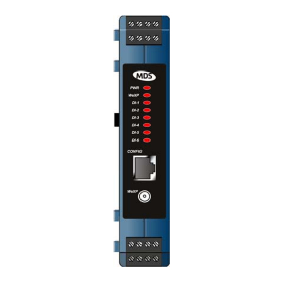
NETio-EB Base Module. Figure 1-5 shows this information for a NETio-XM Expansion Module. A review of these items will assist you in making the connections described later in this section. MDS NETio Installation & Operation Guide MDS 05-4457A01, Rev. A... - Page 17 Figure 1-5. Expansion Module Interface Connectors & LEDs (Typical Model) Together, the NETio Base and Expansion modules offer deployment alternatives that are uniquely scalable to a user’s I/O count, distance and location requirements. MDS 05-4457A01, Rev. A MDS NETio Installation & Operation Guide...
-
Page 18: Din Rail Mounting & Removal
Users with a mixture of equipment requiring Ethernet and serial data Multiple Services interfaces can employ a combination of both NETio modules and MDS entraNET Remotes communicating with a common MDS entraNET Access Point. DIN RAIL MOUNTING & REMOVAL NETio Base and Expansion Modules are equipped for direct mounting to a 35 mm DIN rail without the need for tools. - Page 19 Invisible place holder Figure 1-7. Removal of NETio Equipment from DIN Rail (Pull down on tab and swing bottom of unit away from rail) MDS 05-4457A01, Rev. A MDS NETio Installation & Operation Guide...
-
Page 20: Accessories
1.6 ACCESSORIES MDS NETio equipment may be used with one or more of the accesso- ries listed in Table 1-1. Contact the factory for ordering details. Table 1-1. Accessories Accessory Description MDS Part No. AC Power A small power supply designed for continuous... - Page 21 SMA M to N Male 50 OHM RG142B Coax Assy 97-2036A25 Assembly 36 IN Coaxial Cable SMA Female to SMA Right Angle Coax 97-2036A26 Assembly Adapter Whip Antenna 2.4 GHz Antenna with SMA Male Conn. 97-4278A10 MDS 05-4457A01, Rev. A MDS NETio Installation & Operation Guide...
- Page 22 MDS NETio Installation & Operation Guide MDS 05-4457A01, Rev. A...
-
Page 23: Configuring Wireless System Parameters
2.7.4 Main Menu ................38 2.7.5 Network Configuration Menu ............ 39 2.7.6 Wireless MAC Configuration Menu .......... 39 2.7.7 IP Configuration Menu ............. 40 2.8 ACCESSING NETio UNITS VIA AN entraNET AP ....41 MDS 05-4457A01, Rev. A MDS NETio Installation & Operation Guide... - Page 24 2.8.1 Wireless Network Menu ............42 2.8.2 Remote Management Menu ............. 43 2.8.3 Over-the-Air Configuration of Remotes ........44 MDS NETio Installation & Operation Guide MDS 05-4457A01, Rev. A...
-
Page 25: Introduction
NETio equipment. The NETio modules may also be installed on DIN rails if desired (see “ DIN RAIL MOUNTING & REMOVAL” on Page 10). MDS 05-4457A01, Rev. A MDS NETio Installation & Operation Guide... -
Page 26: Netio Backplane Communication
(+) on the left and negative on the right. NOTE: When multiple modules are connected via the backplane connector, all modules are powered via the Base Module only. Do not connect power to each of the Expansion Modules. MDS NETio Installation & Operation Guide MDS 05-4457A01, Rev. A... -
Page 27: Set Basic Configuration Of The Netio Base Module
The following instructions give a summary of the basic settings for a NETio Base Module. NOTE: All NETio configuration can be performed over-the-air through an MDS entraNET AP. Section explains the menu selection needed. If this method is used, the Network Address and Unit ID must be set in each Base Module first. -
Page 28: Starting Information Screen
This screen provides a read-only overview of the Base Module’s current operating conditions. Quick Start Select to go the Main Menu. Refer to Section 2.3.2, Main Menu Step #3: for detailed information. MDS NETio Installation & Operation Guide MDS 05-4457A01, Rev. A... - Page 29 —Shows the Network Address of the MDS Network Address entraNET network to which this Unit belongs. The Network Address is essential for association to an MDS entraNET Access Point. All Units in a system must have the exact same address.
-
Page 30: Main Menu
2.3.3 Wireless Configuration Menu Depending on the NETio capability options chosen, there may be one configuration task to be performed here, or there may be two. One task MDS NETio Installation & Operation Guide MDS 05-4457A01, Rev. A... -
Page 31: Entranet Configuration Menu
The entraNET Configuration Menu allows access to all NETio entraNET radio-class parameters and provides a review of radio perfor- mance data. Quick Start Select to go to the Basic Configuration Menu (Section 2.3.5.) Step #6: MDS 05-4457A01, Rev. A MDS NETio Installation & Operation Guide... -
Page 32: Basic Configuration Menu
AP. Proceed to Section 2.3.6, Quick Start Step # 8 if your Base Module is equipped with WeXP communication; otherwise go to Section 2.4, Quick Start Step # 10. MDS NETio Installation & Operation Guide MDS 05-4457A01, Rev. A... -
Page 33: Wexp Configuration Menu
Base Module. This name will also be configured into each Wireless Expansion Module that you wish to associate with this Base Module. The WeXP channel, power level and timeout limit (for failsafe applications) may also be set here. MDS 05-4457A01, Rev. A MDS NETio Installation & Operation Guide... -
Page 34: Wireless Expansion Module Configuration
IDs. You can assign the WeXP Address as described in Section 2.4.3. Method 2—Connect a PC to the configuration port (RJ-11 modular) on the front of the Expansion Module and establish a HyperTerminal ses- MDS NETio Installation & Operation Guide MDS 05-4457A01, Rev. A... -
Page 35: Assigning Module Ids
Selecting the letter associated with a module takes you to its configura- tion screen. Quick Start Select to proceed to the Unconfigured/Conflicting Modules Menu Step #10: (refer to Section 2.4.1), if shown. Otherwise, proceed to Section 2.4.3, Quick Start Step 13. MDS 05-4457A01, Rev. A MDS NETio Installation & Operation Guide... - Page 36 Network Menu, but it lists only modules which are not configured or are improperly configured. NOTE: In most cases, newly-installed Expansion and Base Modules will initially appear on the Conflicting/Unconfigured Modules list. MDS NETio Installation & Operation Guide MDS 05-4457A01, Rev. A...
-
Page 37: Id Conflict List Menu
Modules connected through the PCB will be displayed as base in the list. • —Profile of I/O points available for use. (Profile is I/O Layout provided for information only on this screen). MDS 05-4457A01, Rev. A MDS NETio Installation & Operation Guide... -
Page 38: Conflict (Resolution) Menu
Base Module, for example: a WeXP connec- tion or through the Power and Communication Bus (PCB). Modules connected through the PCB will be displayed as base • —Description of conflict source. Conflict Reason MDS NETio Installation & Operation Guide MDS 05-4457A01, Rev. A... -
Page 39: Configuring Wexp Wireless Expansion Modules
2-14) is where all NETio Module parameters can be set or viewed, including I/O point parame- ters. Quick Start Select A and go to the I/O Module Menu (proceed to Section 2.4.5) Step #14: MDS 05-4457A01, Rev. A MDS NETio Installation & Operation Guide... -
Page 40: I/O Module Menu
Figure 2-15. Module Menu 2.4.6 Check for Normal Operation When all modules have been configured, you should use all modules in the I/O Network Menu. Note that you will only see Wireless Expansion MDS NETio Installation & Operation Guide MDS 05-4457A01, Rev. A... -
Page 41: Using & Configuring The Entranet Ap (If Present)
An entraNET AP is often used with NETio for payload communication. All NETio parameters and menus can be accessed over the air through an entraNET AP. For comprehensive information on the entraNET radio, please refer to MDS manual 05-4055A01. MDS 05-4457A01, Rev. A MDS NETio Installation & Operation Guide... -
Page 42: Initial Setup
NETio setup and configuration. Additional sections of this chapter cover NETio access to the AP. Figure 2-17 shows the interface connectors present on an MDS entraNET AP transceiver. Review these items before making the con- nections described in this section. -
Page 43: Measure & Connect Dc Power
AP for operation with NETio radios. For detailed AP instruc- tions and menu navigation, refer to MDS publication 05-4055A01. NOTE: Firmware release 4.1.9 or higher is required for an MDS entraNET AP to communicate with a NETio Remote. MDS 05-4457A01, Rev. A... -
Page 44: Log-In & Configuration At Entranet Ap
Press ENTER 6. At the prompt, enter the password. ( is the default Password admin password). Press Upon successful log-in, the Starting Infor- ENTER mation Screen appears. MDS NETio Installation & Operation Guide MDS 05-4457A01, Rev. A... -
Page 45: Set Key Ap Parameters
Net Address case. are set only if IP/Ethernet connections will IP Address Netmask be used. A complete list of AP commands appears in the MDS entraNET Manual (Part Number 05-4055A01). Table 2-1. Key AP Parameters & Defaults Menu Item Mgt. System Location... -
Page 46: Main Menu
Quick Start Select to go to the Network Configuration Menu. Proceed to Sec- Step #17: tion 2.7.5, Network Configuration Menu. Invisible place holder Figure 2-21. Main Menu MDS NETio Installation & Operation Guide MDS 05-4457A01, Rev. A... -
Page 47: Network Configuration Menu
Figure 2-22. Network Configuration Menu (From Access Point) The Network Configuration Menu is subdivided into the sections listed below. For additional details on these settings, refer to the MDS entraNET manual (Part No. 05-4055A01). • —Allows viewing/setting the transceiver’s IP IP Configuration... -
Page 48: Ip Configuration Menu
Quick Start Select and enter the Net Address. MDS recommends using the last Step #19: 4 digits of the AP’s serial number as the Net Address. Next, proceed to Section 2.7.7 if IP/Ethernet will be used. Other- wise, proceed to Section 2.8. -
Page 49: Accessing Netio Units Via An Entranet Ap
Figure 2-24. IP Configuration Menu • —Essential for connectivity (User Review Recommended) IP Address to the MDS entraNET menu system via the port or over the air. Enter any valid IP address that will be unique within the net- work. [ 192.168.1.1... -
Page 50: Wireless Network Menu
AP. Select D to review a summary of all radios associated with the AP including their Unit IDs and radio type. A typical sample summary screen is shown in Figure 2-28. MDS NETio Installation & Operation Guide MDS 05-4457A01, Rev. A... -
Page 51: Remote Management Menu
2.8.2 Remote Management Menu The Remote Management Menu (Figure 2-28) provides a portal to each Remote radio as well as menus and tools used for updating remote radio firmware and programming. MDS 05-4457A01, Rev. A MDS NETio Installation & Operation Guide... -
Page 52: Over-The-Air Configuration Of Remotes
NETio Unit. When configuration is completed, remember to type * three times to return to the AP configurator (see Figure 2-29). Figure 2-29. HyperTerminal Command Screen MDS NETio Installation & Operation Guide MDS 05-4457A01, Rev. A... -
Page 53: O Point Configuration
3.3.1 Setting the Source Field for Mapping ........53 3.3.2 Mapping Between NETio Units ..........55 3.4 FAILSAFE SETTINGS ..............55 3.4.1 Configuring Failsafe Settings ............56 3.4.2 Configuring Failsafe Timeouts ...........57 WeXP Failsafe Timeout ..............57 MDS 05-4457A01, Rev. A MDS NETio Installation & Operation Guide... - Page 54 MDS NETio Installation & Operation Guide MDS 05-4457A01, Rev. A...
-
Page 55: I/O Point Configuration
WeXp LED blinks to indicate that it is being accessed for configuration. Quick Start Select the letter associated with the module containing the I/O point Step #24: to be configured. Proceed to Section 3.2.4. MDS 05-4457A01, Rev. A MDS NETio Installation & Operation Guide... -
Page 56: I/O Module Configuration Menu
If a Discrete Input is selected, proceed to Section 3.2.2. If a Discrete Output is selected, proceed to Section 3.2.4 If an Analog Input is selected, proceed to Section 3.2.3 MDS NETio Installation & Operation Guide MDS 05-4457A01, Rev. A... -
Page 57: Discrete Input Menu
—The current value (voltage or current) of this point. Value • — A composite of the Unit ID, Module ID and Point Address Point (address) Number. The values are separated by com- mas. MDS 05-4457A01, Rev. A MDS NETio Installation & Operation Guide... -
Page 58: Analog Input Menu
• —The present value in A/D counts for this point Value address. • —Address used to identify this input point. For- Point Address mat: Unit ID, Module ID, Point Number] MDS NETio Installation & Operation Guide MDS 05-4457A01, Rev. A... -
Page 59: Discrete Output Menu
NETio module, including the same module in which this point is located. Format: Unit ID, Module ID, Point Number] • —The current value (voltage or current) of this point. Value MDS 05-4457A01, Rev. A MDS NETio Installation & Operation Guide... -
Page 60: Analog Output Menu
• —Address used to identify this input point. For- Point Address mat: Unit ID, Module ID, Point Number] • —The present value in A/D counts for this point Value address. MDS NETio Installation & Operation Guide MDS 05-4457A01, Rev. A... -
Page 61: Mapping Inputs To Outputs For Signal Extension And Regeneration
Mapping is accomplished simply by setting the address of the input signal into the source field in an output point. Figure 3-8 shows the Analog Output Menu with the source field set to NO SOURCE MDS 05-4457A01, Rev. A MDS NETio Installation & Operation Guide... - Page 62 3-8), and select C to enter the source address. 2. NETio prompts you for three entries as follows: a. The Unit ID of the Source Signal. (In this example, the Unit ID is 7771.) MDS NETio Installation & Operation Guide MDS 05-4457A01, Rev. A...
-
Page 63: Mapping Between Netio Units
1. WeXP—Wireless communication between Wireless Expansion Modules and a NETio Base Module within a NETio Unit. 2. NETio entraNET Radio—Wireless communication over longer ranges between NETio Units. MDS 05-4457A01, Rev. A MDS NETio Installation & Operation Guide... -
Page 64: Configuring Failsafe Settings
For an Analog Output the Failsafe Mode options are: —Ramp output to the highest value in the range. HIGH —Ramp output to the lowest value in the range. —Holds last value output prior to communication failure. HOLD MDS NETio Installation & Operation Guide MDS 05-4457A01, Rev. A... -
Page 65: Configuring Failsafe Timeouts
Main Menu>>Wireless Configuration>>WeXP Configuration Invisible place holder Figure 3-12. WeXP Configuration Menu The default value is 5000 ms (5 seconds) The value should not be set below 1000 ms (1 second). MDS 05-4457A01, Rev. A MDS NETio Installation & Operation Guide... - Page 66 The default WeXP timeout setting may be changed by selecting from the menu. The default setting is 5000 ms (5 seconds). This value should not be set lower than 1000 ms (1 second). MDS NETio Installation & Operation Guide MDS 05-4457A01, Rev. A...
-
Page 67: Wiring & Terminations
4.2 I/O POINTS WIRING & TERMINATION........62 4.2.1 Analog Input Wiring ..............62 Current Mode................. 62 Voltage Mode................. 63 4.2.2 Discrete Points Wiring .............. 63 4.2.3 Module Wiring Diagrams ............64 MDS 05-4457A01, Rev. A MDS NETio Installation & Operation Guide... - Page 68 MDS NETio Installation & Operation Guide MDS 05-4457A01, Rev. A...
-
Page 69: I/O & Power Connections
NETio modules are available in a variety of configurations depending on the requirements of a particular application. Table 4-1 lists the avail- able modules and shows the functions supported by each type. In addi- MDS 05-4457A01, Rev. A MDS NETio Installation & Operation Guide... -
Page 70: I/O Points Wiring & Termination
I/O application. The second view is specific, with connections shown based on actual module types. These drawings do not reflect all possible wiring schemes or applications. Please contact MDS Technical Services if additional guidance is required. 4.2.1 Analog Input Wiring... -
Page 71: Voltage Mode
Discrete Input MDS NETio POWER w/External Power Supply Base or SUPPLY Expansion LOAD Discrete Output MDS NETio POWER w/External Power Supply Base or SUPPLY Expansion Figure 4-7. 2-Wire Discrete Wiring MDS 05-4457A01, Rev. A MDS NETio Installation & Operation Guide... -
Page 72: Module Wiring Diagrams
Ain – Dout 1 – Din 1 – 24 ISO + Aout + Dout 2 + Din 2 + 24 ISO – Aout – Dout 2 – Din 2 – MDS NETio Installation & Operation Guide MDS 05-4457A01, Rev. A... - Page 73 Ain – Dout 1 – Din 1 – 24 ISO + Aout + Dout 2 + Din 2 + 24 ISO – Aout – Dout 2 – Din 2 – MDS 05-4457A01, Rev. A MDS NETio Installation & Operation Guide...
- Page 74 Din 3 – Din 5 – 24 ISO + Din 2 + Din 4 + Din 6 + 24 ISO – Din 2 – Din 4 – Din 6 – MDS NETio Installation & Operation Guide MDS 05-4457A01, Rev. A...
- Page 75 Dout 3 – Dout 5 – 24 ISO + Dout 2 + Dout 4 + Dout 6 + 24 ISO – Dout 2 – Dout 4 – Dout 6 – MDS 05-4457A01, Rev. A MDS NETio Installation & Operation Guide...
- Page 76 Din 2 + Din 4 + 24 ISO – Ain 2 – Din 2 – Din 4 – NOTE: There is no Type 5 Module offered for the NETio product line. MDS NETio Installation & Operation Guide MDS 05-4457A01, Rev. A...
- Page 77 Din 1 + POWER – Aout 2 Dout 1 – Din 1 – GROUND Ain 1 Dout 2 + Din 2 + GROUND Ain 2 Dout 2 – Din 2 – MDS 05-4457A01, Rev. A MDS NETio Installation & Operation Guide...
- Page 78 POWER – Ain 1 – Dout 1 – Din 1 – GROUND Ain 2 + Dout 2 + Dout 3 + GROUND Ain 2 – Dout 2 – Dout 3 – MDS NETio Installation & Operation Guide MDS 05-4457A01, Rev. A...
-
Page 79: Configuring Serial And Ip/Ethernet
AND IP/ETHERNET COMMUNICATIONS 5 Chapter Counter Reset Paragraph 5.1 CONFIGURING SERIAL AND IP/ETHERNET COMMUNICATIONS..............73 5.1.1 Configuring the NETio Serial Port ..........73 5.1.2 Configuring the IP Ethernet Port ..........75 MDS 05-4457A01, Rev. A MDS NETio Installation & Operation Guide... - Page 80 MDS NETio Installation & Operation Guide MDS 05-4457A01, Rev. A...
-
Page 81: Configuring Serial And Ip/Ethernet Communications
NETio Unit is always a remote radio to an entraNET AP. Most of the wireless network configuration for Serial and IP/Ethernet communication is performed at the entraNET AP. Refer to the MDS entraNET manual (MDS publication 05-4055A01) for configuration steps. - Page 82 • —To be supplied. Seamless Mode • This command sets / displays the transceiver’s Flow Control— flow control status. Options are as follows: MDS NETio Installation & Operation Guide MDS 05-4457A01, Rev. A...
-
Page 83: Configuring The Ip Ethernet Port
Port for communication, begin at the Main Menu (Figure 5-1) and select E. The Ethernet Port Menu shown in Figure 5-3 will be displayed. Figure 5-3. Ethernet Port Menu Select to enable or disable the Ethernet port. A) Mode MDS 05-4457A01, Rev. A MDS NETio Installation & Operation Guide... - Page 84 MDS NETio Installation & Operation Guide MDS 05-4457A01, Rev. A...
-
Page 85: Maintenance And Support Functions
6.4 DEVICE, MODULE and I/O POINT DESCRIPTIONS ..... 84 6.4.1 Changing the NETio Device Name .......... 84 6.4.2 Changing NETio Module and I/O Point Names ......85 6.5 dBm-WATTS-VOLTS CONVERSION CHART ......86 MDS 05-4457A01, Rev. A MDS NETio Installation & Operation Guide... -
Page 86: Introduction
The default value for NETio’s entraNET radio is 30 dBm (1 watt). To change this value, make the following selections from the Main Menu: . The menu Wireless Configuration>>entraNET Radio>>Basic Configuration shown in Figure 6-2 appears. MDS NETio Installation & Operation Guide MDS 05-4457A01, Rev. A... -
Page 87: Performance, Statistics, Rssi Information
To reach this menu, select Sta- tistics/Events>>Performance Statistics Invisible place holder Figure 6-3. Performance Statistics Menu To review entraNET radio information, select entraNET Radio Statis- tics. The menu shown in Figure 6-4 is presented. MDS 05-4457A01, Rev. A MDS NETio Installation & Operation Guide... -
Page 88: Setting Approved Access Points And Passwords
NETio. If data encryption is enabled, it can also be modified. These parameters are located in the Security menu ( ) shown in Figure 6-5. Main Menu>>Security Invisible place holder Figure 6-5. Security Menu MDS NETio Installation & Operation Guide MDS 05-4457A01, Rev. A... -
Page 89: Maintenance/Tools/Date And Time
The few remaining param- eters are accessed from the I/O Module Configuration Menu shown in Figure 6-7 Main Menu>>I/O Network>>I/O Module Configuration MDS 05-4457A01, Rev. A MDS NETio Installation & Operation Guide... -
Page 90: View/Set Expansion Module Wexp Rf Power
6.3.2 Changing Base Module WeXP RF Output Power The WeXP output power for a Base Module is configured from the WeXP Configuration Menu shown in Figure 6-9 Main Menu>>Wireless Configuration>>WeXP Configuration MDS NETio Installation & Operation Guide MDS 05-4457A01, Rev. A... -
Page 91: Changing Wexp Rf Channel
I/O Module Configuration Menu (Figure 6-7 on Page 82). To view the performance, select Module Perfor- from this menu. The menu shown in Figure 6-10 mance/Statistics appears. MDS 05-4457A01, Rev. A MDS NETio Installation & Operation Guide... -
Page 92: Device, Module And I/O Point Descriptions
I/O Points by their location, type of service, or signal ID. 6.4.1 Changing the NETio Device Name The Owner, Device Name and Device Location can be modified in the Device Menu shown in Figure 6-12 Main Menu>>Device MDS NETio Installation & Operation Guide MDS 05-4457A01, Rev. A... -
Page 93: Changing Netio Module And I/O Point Names
Point ID Tag Menus, an example of which is shown in Figure 6-13. Invisible place holder Figure 6-13. Example of Point ID Tag Selection (This example shows Discrete Input Menu) MDS 05-4457A01, Rev. A MDS NETio Installation & Operation Guide... -
Page 94: Dbm-Watts-Volts Conversion Chart
10.0 -136 10mW -137 2.25 .1μW -138 6.4mW .001nW -139 .500 -140 .01ƒW .445 5.75 .400 3.2mW .355 2.5mW 1.25 .320 2.0mW 1.18 .280 1.6mW 1.00 3.51 .252 1.25mW 0.90 MDS NETio Installation & Operation Guide MDS 05-4457A01, Rev. A... - Page 95 IN CASE OF DIFFICULTY... MDS products are designed for long life and trouble-free operation. However, this equipment, as with all electronic equipment, may have an occasional component failure. The following informa- tion will assist you in the event that servicing becomes necessary.
- Page 96 Microwave Data Systems Inc. 175 Science Parkway Rochester, NY 14620 General Business: +1 585 242-9600 FAX: +1 585 242-9620 Web: www.microwavedata.com A product of Microwave Data Systems Inc.
Need help?
Do you have a question about the NETio Series and is the answer not in the manual?
Questions and answers