
Related Manuals for C2Dx T/PUMP TP700


Summary of Contents for C2Dx T/PUMP TP700
- Page 1 Maintenance Manual T/PUMP ® SERIES LOCALIZED TEMPERATURE THERAPY SYSTEM TP700 TP700C www.c2dx.com 2021/10 Rev 1 101176 Rev 1...
- Page 3 Warning non-ionizing radiation Catalogue number Serial number Manufacturer For US Patents see www.C2Dx.com/patents Dangerous voltage Type BF applied part Medical Equipment Recognized by Underwriters Laboratories LLC With Respect to Electric Shock, Fire, and Mechanical Hazards only in accordance with UL 60601- 1: 2003 and CAN/CSA-C22.2 No.
-
Page 5: Table Of Contents
Fluid system .................................................... 24 Theory of operation ................................................25 Reservoir ....................................................26 Upper front and rear housing ..........................................26 PC Board ....................................................26 Heater kit assembly ................................................27 Heater assembly .................................................. 27 T/Pump Temperature Therapy Pump assembly ..............................29 ® 101176 Rev 1 c2dx.com... -
Page 6: Warning / Caution / Note Definition
Provides special information to make maintenance easier or important instructions clearer. Note: 101176 Rev 1 c2dx.com... -
Page 7: Summary Of Safety Precautions
Do not place unprotected circuit boards on the floor. • Do not use the product next to or stacked with other equipment. If next to or stacked is necessary, observe the product to verify normal operation in the configuration in which it used. 101176 Rev 1 c2dx.com... -
Page 8: Introduction
Introduction This manual assists you with the maintenance of your C2Dx product. Read this manual before maintaining this product. ® Set methods and procedures to educate and train your staff on the safe maintenance of this product. CAUTION Do not modify the product or any components of the product. Modifying the product can cause unpredictable operation resulting in injury to patient or operator. -
Page 9: Specifications
Power cord International (harmonized) 3 wire cord set Dual hose 10 ft 305 cm Current leakage, maximum 100 μA Ground resistance, maximum 0.5 mΩ Voltage 120 VAC ±10% Electrical requirements Frequency: 60 Hz Current in amperes 101176 Rev 1 c2dx.com... -
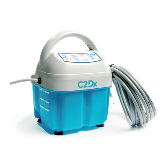
Page 10: Product Illustration
Storage and transportation 90°F 120°F (32.2°C) (48°C) Ambient operating temperature 60°F -20°F (15.6°C) (-28°C) C2Dx reserves the right to change specifications without notice. ® Product illustration Handle vents Hose storage Keypad Cord storage Flow indicator Tethered open cap Warm or cool delivery... -
Page 11: Product Keypad
® 555 E Eliza St, Ste A Schoolcraft, MI 49087 To view your operations or maintenance manual online, see www.c2dx.com/manuals Have the serial number (A) of your C2Dx product available when calling C2Dx Customer Service or Technical ® ® Support. Include the serial number in all written communication. -
Page 12: Serial Number Location
Introduction Serial number location 101176 Rev 1 c2dx.com... -
Page 13: Cleaning
Press the On/Standby button to start the pump. Circulate the solution for one hour. Drain the solution from the reservoir. Rinse and drain the reservoir with water. 10. Dry the reservoir inside and outside with a dry, lint free cloth. 101176 Rev 1 c2dx.com... -
Page 14: Quick Reference Replacement Parts
Quick reference replacement parts These parts are currently available for purchase. Call C2Dx Customer Service: 888-902-2239 for availability and ® pricing. Item Serial Number Description Quantity 100822001 KIT: Upper front & Rear Housing. Includes both Front & Rear plastic housing, Label, Membrane Panel (TP700 / TP700C) - Page 15 Label, Ratings Professional (TP700 ) 100289003 Label, Ratings Professional with quick disconnects (TP700C) 100292000 Clip, Cord 100378000 Cap (for Impeller Pin) 100578000 Label, Danger 100256001 Heater Cartridge Assembly 0000-001-083 Label, product barcode TP700C 0000-001-084 Label, product barcode TP700 101176 Rev 1 c2dx.com...
-
Page 16: Accessories
Accessories These accessories may be available for use with your product. Confirm availability for your configuration or region. Call C2Dx Customer Service: 888-902-2239. ® Test tools Catalog Number Product Name Number in Carton TPT9 Flow and Temperature Tester 100925000 Test Probe Assembly... - Page 17 For use 22 in. (56 cm) 15 in. (38 cm) Non-woven fabric on with Colder both sides connectors 8002-062-626 For use 26 in. (66 cm) 18 in. (46 cm) Non-woven fabric on with Colder both sides connectors 101176 Rev 1 c2dx.com...
-
Page 18: Preventive Maintenance
On/Standby button to stop the test, then restart the procedure. If after a second attempt you cannot get the expected result, press On/Standby button to stop the test. Unplug the T/Pump ® Temperature Therapy Pump and call your dealer or contact C2Dx Technical Support Department for help. ® 101176 Rev 1... -
Page 19: Functional Check And Safety Inspection Form
• Vacuum cleaner or air compressor • Functional check and safety inspection form on page 15 Note: To order any of the parts listed, contact your dealer or contact C2Dx customer service. ® Functional check and safety inspection form Inspection forms vary from hospital to hospital. The following sample form is intended as a guide to record the important parameters. -
Page 20: Functional Check Setup - Clik-Tite
TPT9, 7 gph (26.5 lph) minimum. Read at top of the float (E). Functional check setup - Colder connection Note: If the flow meter is connected in reverse, the flow meter will indicate no flow. Reverse the pump hose connections to change the direction of the flow. 101176 Rev 1 c2dx.com... -
Page 21: Internal Pump Inspection
Functional check setup - Clik-Tite connectors on page 16 Functional check setup - Colder connection on page 17). ® Straighten the pad and hose. Open the hose clamps. Open the fill cap on top of the pump. 101176 Rev 1 c2dx.com... -
Page 22: Backup Limit Thermostat Test
Using a #2 Phillips screwdriver, remove and save the 9 screws that secure the tray to the reservoir. P/N 90018082 (x4) P/N 90018075 (x5) Unplug the Temperature Sensor. Install the test probe (Figure 3 on page 18). Make sure that you position the test probe away from the motor fan. 101176 Rev 1 c2dx.com... -
Page 23: Water Leak Check
Figure 5 on page 25 item 6. You can access the ground through the hole where the hose connects to the pump (see Figure 4 on page 20). Notes: The value should not be more than 0.5 ohm. 101176 Rev 1 c2dx.com... -
Page 24: Current Leakage Check
(See Figure 4 Access to ground on page 20) the hose connects to the pump. • The highest reading should be less than 100μA. Figure 4: Access to ground Record the highest reading. 10. Disconnect the current leakage meter. 101176 Rev 1 c2dx.com... -
Page 25: Troubleshooting
Reference “Flow indicator light is ON” are ON with T/Pump Temperature more than 5 minutes, thus goes to ® Correct the problem, and press the Therapy Pump NOT pumping Standby On/Standby to put the unit back into Run mode. 101176 Rev 1 c2dx.com... - Page 26 If Power is present and thermostat is CLOSED, heater is probably defective. Cold heater resistance is approximately 49 ohms (120V). Replace heater if required. Perform Functional checks on page 14. If Power is present and thermostat is OPEN, thermostat is probably 101176 Rev 1 c2dx.com...
-
Page 27: Wiring Diagram
Replace Clik-Tite connector Water LEAKS from hose connectors ® Male: P/N: 03887001 Female P/N: 03884001 Snap Clik-Tite connector SHUT ® Secure pad connection to pump (See quick disconnects). Replace connectors or pad if defective. Wiring diagram 101176 Rev 1 c2dx.com... -
Page 28: Service
Always use ESD protective equipment before opening antistatic bags and servicing electronic parts. • Do not place unprotected circuit boards on the floor. Always ship back circuit boards to C2Dx in the same antistatic bags that the new boards were originally Note: ®... -
Page 29: Theory Of Operation
Figure 5: T/Pump Temperature Therapy Pump service items ® PC board (temperature controller) Brass manifold block Manifold backup limit thermostat Return hose fitting Pump motor Temperature sensor Tray assembly Housing front assembly Cartridge heater Ribbon to front keypad 101176 Rev 1 c2dx.com... -
Page 30: Reservoir
Remove the Temperature Sensor (Figure 5 on page 25, item 8) from the PC Board. Remove the six wires from the PC Board. Remove the three screws from the PC Board. 10. Remove and discard the PC Board. 101176 Rev 1 c2dx.com... -
Page 31: Heater Kit Assembly
Make sure wires are routed away from the cooling fan blades. For proper screw size and location for reservoir and housing, refer to parts illustration and replacement parts list. Transfer the serial number to the new reservoir and cover the serial number label window 101176 Rev 1 c2dx.com... - Page 32 When needed, route the membrane ribbon (A) to the PCB Kit (B) from the Front Housing (C) (Figure 6 on page 28). This prevents interference between the ribbon and moving components.. Figure 6: Ribbon cable Verify proper operation before returning the product to service. 101176 Rev 1 c2dx.com...
-
Page 33: T/Pump ® Temperature Therapy Pump Assembly
T/Pump Temperature Therapy Pump assembly ® 101176 Rev 1 c2dx.com... - Page 34 T/Pump Temperature Therapy Pump assembly ® 101176 Rev 1 c2dx.com...
- Page 35 Housing with Membrane Panel ( TP700 / TP700C ) 100821001 KIT: Heater Assembly. Includes Brass Manifold, 2 O-Rings, 4 Fittings. ( TP700 / TP700C ) 100820000 KIT: Reservoir Assembly. Includes Reservoir, Gasket, Rubber Feet, Label. 03394000 Fitting, manifold 03791001 Strap assembly - hose 04152000 101176 Rev 1 c2dx.com...
- Page 36 Housing, front assembly 100142000 Housing, rear assembly 100152000 O-Ring, reservoir 100261000 Motor/plate assembly 100267000 Cord, power assembly (gray) 39/40 100269001 Membrane panel - professional 100275000 Cap, tethered, rivet assembly 101158000 Magnet driver assembly 43/44 100288001 Label, instruction professional 101176 Rev 1 c2dx.com...
- Page 37 Clip, cord 100378000 Cap (for Impeller Pin) 100578000 Label, danger 100706000 Wiring harness 100706001 Wiring harness 100706002 Wiring harness 100144000 Heater assembly - classic 120V/ 60Hz 0000-001-083 Label, product barcode TP700C 0000-001-084 Label, product barcode TP700 101176 Rev 1 c2dx.com...
- Page 39 C2Dx, Inc. 555 East Eliza Street, Ste. A Schoolcraft, MI 49087 www.c2dx.com 2021/10 Rev 1 101176 Rev 1...
Need help?
Do you have a question about the T/PUMP TP700 and is the answer not in the manual?
Questions and answers