
Summary of Contents for schroff nvent 11850-029
- Page 1 1U 4-slot MTCA Shelf User‘s Manual Product Number: 11850-029 July 2021 Doc-No: 63972-397_R1.1...
- Page 2 November 2020 Initial release R1.1 July 2021 Pinout eCLK Module corrected Impressum: Schroff GmbH Langenalber Str. 96 - 100 75334 Straubenhardt, Germany The details in this manual have been carefully compiled and checked - supported by certified Quality Management System...
-
Page 3: Table Of Contents
11850-029 Safety ........................1 Safety Symbols used in this document................1 General Safety Precautions ....................1 References and Architecture Specifications..............1 Hardware Platform ....................2 Introduction ........................2 Front and Rear View......................3 ESD Wrist Strap Terminal ....................3 Backplane ......................... 4 Backplane Topology ...................... - Page 4 11850-029 R1.1, July 2021...
-
Page 5: Safety
11850-029 1 Safety The intended audience of this User’s Manual is system integrators and hardware/software engineers. 1.1 Safety Symbols used in this document Hazardous voltage! This is the electrical hazard symbol. It indicates that there are dangerous voltages inside the Shelf. -
Page 6: Hardware Platform
11850-029 2 Hardware Platform 2.1 Introduction The 4-slot SCHROFF MicroTCA System is designed to accommodate two double Mid-size AMC modules with RTM and 2 Single Mid-size AMCs for maximum computing power in minimal space. The integrated eMCH (Embedded MicroTCA Carrier Hub), power supply and cooling unit allow easy servicing.... -
Page 7: Front And Rear View
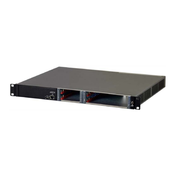
11850-029 2.2 Front and Rear View Figure 1: Front and RearView eMCH AC input with Mains/line switch and fuse AMC slots 1 & 3 AMC slots 2 & 4 Air filter ESD Wrist Strap Terminal Fans rear section RTM slots Fans front section Ground Terminal (Equipotential bonding) 12 Connector for 3rd party eCLK module... -
Page 8: Backplane
11850-029 3 Backplane 3.1 Backplane Topology Fabric 1/A to AMC Port 0 Fabric 2/A to AMC Port 0 AMC Port 2 (SATA) SATA-Headers (on eCLK) AMC Port 3 (SATA) M.2 S-ATA module (3.3V main power) Configuration 1 AMC1 port 4-5 to AMC4 port 4-5; AMC Port 4-5 AMC1 port 6-7 to AMC3 port 4-5;... -
Page 9: Backplane Features
11850-029 3.2 Backplane Features • GbE Links from MCH to all AMC Slots • Direct S-ATA / SAS connections: - AMC 1 <-> AMC 3: Port 2 - AMC 2 <-> AMC 4: Port 3 - AMC 1 & 3: Port 3 <-> SATA Headers on eCLK connector •... -
Page 10: Third Party Clock Module
11850-029 3.5 Third party clock module The system provides a connector and mounting space for a third party clock module. Clock Module Connector Pinout Pin Signal name Direction Functionality/Description Notes PS1_eClock# Presence signal of the eClock module, active low GA0 / RFU passive Geographic Address 0 / Reserved for IPMBL-SCL-eClock inout... - Page 11 11850-029 Pin Signal name Direction Functionality/Description Notes 33 GND Ground 34 MLVDS-19-RX- inout Bus LVDS Port 19 RX- 35 MLVDS-17-RX+ inout Bus LVDS Port 17 RX+ 36 PP power Payload Power 12V Current Capability 2.8A max (derated to 1.5A) 37 MLVDS-17-RX- inout Bus LVDS Port 17 RX- 38 MLVDS-19-TX+...
-
Page 12: Cooling
11850-029 4 Cooling 4.1 Air Filter Figure 2: Air Filter Air Filter 4.2 Air filter swap The system provides a replaceable air filter. The air filter can be pulled out after removing the top cover. The filter meets the requirements of the Telcordia Technologies Generic Requirements GR-78- CORE specification. -
Page 13: Power Supply
11850-029 4.4 Power Supply Hazardous voltage! Parts of the power supply may be exposed with hazardous voltage. Always remove mains/line connector before carry out any assembly work. Caution! The unit is designed in accordance with protection class 1! It must therefore be operated with protec- ... -
Page 14: Emch (Embedded Microtca Carrier Hub)
11850-029 5 eMCH (embedded MicroTCA Carrier Hub) The eMCH (embedded MicroTCA Carrier Hub) is intended to provide basic MicroTCA functionality for switching and managing AMC (Advanced Mezzanine Card) modules. It delivers switching and hub functionality for the system fabric gigabit ethernet (GbE) as defined in the AMC.0 standard series.... -
Page 15: Front Panel And Leds
11850-029 5.1 Front Panel and LEDs The eMCH front panel consists of 4 status LEDs for the AMCs, and 2 LEDs (OK, FAIL) for the system’s operation status. In addition to the LEDs, you can find sockets for a RJ45 plug and a micro USB cable. -
Page 16: Command Line Interface (Cli)
11850-029 5.2 Command Line Interface (CLI) The EMCH is providing a low level command line interface (CLI) which allows to set certain operational parameters and to display run time information from the MCH and the system. 5.2.1 COM-Settings The CLI can be accessed over the front MicroUSB port. To establish a connection to a host PC, use a serial terminal program e.g. -
Page 17: Setting The Fat Pipe / Extended Fatpipe Configurations
11850-029 5.3 Setting the fat pipe / extended fatpipe configurations The 2 different fat pipe / extended fat pipe configurations are set via a PCIe MUX. For the setting you must open the configuration menue in eMCH. • Connect your host PC to the USB port and start your terminal program •... - Page 18 11850-029 Cooling parameter: Default fan level: 30 % Enable alternative cooling scheme: FAN speed decrease time: Ethernet interfaces: Front Uplink (RJ45) enabled AMC1 port 0 enabled AMC2 port 0 enabled AMC3 port 0 enabled AMC4 port 0 enabled PCIexpress configuration: 0 (Default) MCH remote interfaces Enable RMCP access (y/n) (RET=y):...
- Page 19 11850-029 Enable alternative cooling scheme (y/n) (RET=n): FAN speed decrease time (min) (RET=120/0x78): Enter default fan level (10-100%) (RET=30/0x1e): ----------------------------------- CFG: configuration modes [ 0] no action [ 1] print complete configuration [ 2] modify MCH global configuration [ 3] modify ShM configuration [ 4] modify CM configuration [ 5] modify SEL configuration [ 6] modify DHCP configuration...
-
Page 20: Firmware Update
11850-029 5.4 Firmware Update The EMCH serves a web based front end to easily upgrade the devices firmware in field. To use this utility, first establish an ethernet link over the EMCH uplink port. If not changed, the standard interface config is as followed: Table 5: Standard interface configuration IP address: 192.168.1.138... -
Page 21: Technical Data
11850-029 6 Technical Data Table 6: Technical Data Physical Dimensions Height 43.60 mm (1 U) Width (with mounting brackets) 482.60 mm (19“) Width (w.o. mounting brackets) 443.60 mm Depth approx. 373 mm Weight Weight completely assembled approx. 5.8 Kg Power Supply Input Voltage 100 VAC to 240 VAC Mains Frequency... -
Page 22: Dimensions
11850-029 6.1 Dimensions 482,60 mm 443,50 mm Technical Data R1.1, July 2021... - Page 24 Schroff GmbH Langenalber Str. 96 - 100 75334 Straubenhardt, Germany +49.7082.794.0 +49.7082.794.200...
Need help?
Do you have a question about the nvent 11850-029 and is the answer not in the manual?
Questions and answers