
Summary of Contents for Parker Hydraulics Hydraguide HGF Series
- Page 1 Hydraulics Hydraguide ™ Hydrostatic Steering System HGF Series Service Procedure Service Manual 2753 Hydraulic Pump/Motor Division...
- Page 2 HGF Design Features Illustration Port Cover Port Manifold Hex Drive Assembly Isolation Manifold Valve Springs Valve Set Metering Ring Rotor Set Drive Link Commutator Set Upper Cover Plate Drive Plate Thrust Bearing Upper Cover & Jacket Tube Assembly Set Input Shaft/Wheel Tube...
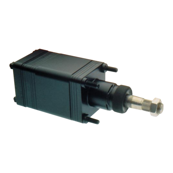
- Page 3 Hydraguide ™ HGF Design Features The model HGF Hydraguide™ power steering unit is Ross' most recent addition to its series of hydrostatic steering products. The HGF combines several advanced features designed to meet industry's needs for improved steering of its construction, industrial, and agricultural vehicles. •...
-
Page 4: Table Of Contents
Table of Contents Page Definitions ..............................1 Introduction ..............................2 Design and Operation...........................3 HGF Hydraguide Steering System ......................4 Troubleshooting Guide..........................5 Troubleshooting Checklists ...........................6 Component Alignment Groove Illustration (Fold-Out) ................7B Exploded View (Fold-Out) ......................... 7C Tools and Material Required for Servicing ....................8 Torque Chart..............................8 Disassembly and Inspection .........................9 Assembly ..............................21... -
Page 5: Definitions
Definitions NOTE: A NOTE provides key infor mation to make a procedure easier or quicker to complete. CAUTION: A CAUTION refers to procedures that must be followed to avoid damaging the HGF or other system components. WARNING: A WARNING REFERS TO PROCEDURES THAT MUST BE FOLLOWED FOR THE SAFETY OF THE VEHICLE DRIVER AND THE PERSON INSPECTING OR REPAIRING THE HGF. -
Page 6: Introduction
Introduction Service Manual for Model HGF This service manual has one purpose: to guide you in maintaining, troubleshooting, and servicing the HGF Hydraguide power steering valve. Material in this manual is organized so you can work on the HGF and get results without wasting time or being confused. -
Page 7: Design And Operation
HGF: Design and Operation (See HGF Design Features and Design Illustration) Satisfactory performance of the overall hydraulic system configurations, each of which brings its own advantages requires a well-engineered installation. The hydraulics to bear in the hydraulic system. must meet the design features of the vehicle and contribute to the operation for which the vehicle was built. -
Page 8: Hgf Hydraguide Steering System
HGF Hydraguide™ Steering system Return Pressure POWER BEYOND OPEN CENTER HYDRAGUIDE ™ STEERING HYDRAGUIDE ™ STEERING HGF Series Service Procedure... -
Page 9: Troubleshooting Guide
Troubleshooting Guide NOTE: Before troubleshooting a steering problem, check service literature published by the vehicle and component manufacturers. Follow their instructions, if given, for checking any component but the HGF Hydraguide unit. Preparation See if something in the steering column is loose or Make your troubleshooting easier by preparing as binding. -
Page 10: Troubleshooting Checklists
Troubleshooting Checklists 1. NOISE NORMAL NOISE A low hissing from the HGF control valve section during a turn A noise from the system relief valve when it is actuated Pump growl from some types of power steering pumps ABNORMAL NOISE A squealing noise during a turn may indicate that the belt or belts should be tightened or replaced A clicking noise during a turn may indicate that some component is loose and shifting under load. - Page 11 HIGH STEERING EFFORT IN BOTH DIRECTIONS Different size tires Vehicle overloaded Low hydraulic fluid level Low flow or pressure from pump Components in steering linkage binding Restriction in fluid return line, or line too small LOST MOTION (LASH) AT THE STEERING WHEEL Steering wheel loose on column Components in steering linkage loose or worn HGF unit loose at mounting...
- Page 12 HGF COMPONENT ALIGNMENT GROOVE ILLULSTRATION COMPONENTS OF THE HGF UNIT WITH ALIGNMENT GROOVES MUST BE ASSEMBLED SO THAT THEIR ALIGNMENT GROOVES ARE POSITIONED AS ILLUSTRATED FOR THE UNIT TO FUNCTION CORRECTLY IF THE HGF UNIT BEING DISASSEMBLED HAD A CONTACT BRUSH ASSEMBLY, NOTE THE RADIAL POSITION OF IT'S HOLE RELATIVE TO ALIGNMENT GROOVED SIDE OF THE UNIT BEFORE DISASSEMBLY AND REASSEMBLE IN THE...
- Page 13 HGF Exploded Assembly View-Typical Item Number Description Nut 5/16 UNF 24 (4) Port Cover Seal Ring (5) Seal Ring (White) O’Ring (3), (4) or (5) Ball-7/32 inch (6mm) dia. Relief valve cartridge Coil spring Plug Hex plug O’Ring, Plug & O’Ring assy. O’Ring Port Manifold Spring, 3/4 inch (19mm) (3)
- Page 14 Use with HGF Assembly View–Typical Nut 5/16 UNF (4) Port Cover & Port Mainfold Kits Seal Ring Seal Ring (White) HGF 016015 X1(5 line) HGF 016016X1 (4 line) 032755 (5) 032832 G103025 9 & 14 Spring Kit “O”Ring (5) Ball 7/32 dia. Plug and “O”...
-
Page 15: Exploded View (Fold-Out)
Tools Materials Required for Servicing HGF Service Manual HGF service ass'y fixture (See Figure 1) Clean, petroleum-based solvent Vise Pliers Screw driver Blunt ended punch 6 pieces of .007 inch (.18 mm) shim stock, approximately Figure 1 .5 inch (13 mm) wide x 1.5 inch (38 mm) long. External retaining ring pliers Tape, plastic electrical CONVERSIONS... -
Page 16: Disassembly And Inspection
HGF: Disassembly and Inspection Preparation before disassembly Before you disassemble the HGF Hydraguide unit or any Remove any contact brush cover (49) contact brush of its parts, read this entire manual. It provides important cover seal (48) and related screw and lock washers (50), information on parts and procedures you will need to and disconnect any horn wire connection to the HGF know to service the HGF. - Page 17 Place HGF unit in 2. To avoid distorting or service fixture damaging the HGF unit, do not clamp it directly into a vise. Clamp a service assembly fixture described in FIGURE 1 securely in a vise, See FIGURE 3, and place the HGF unit, input shaft/wheel tube first, into the service assembly fixture.
- Page 18 Remove port cover 5. Grasp the port cover (2) assembly and lift it from the unit. Discard three, four, or five seal rings (4) and seal ring (3) or if included white seal ring (3A). See FIGURE 7. Remove loose check ball (52) from top of port manifold (8) if included.
- Page 19 Inspect port 11. Inspect the ground surfaces of manifold the port manifold (8). You should notice a "normal" polished pattern due to the rotation of the valve plate (13) and hex drive assembly (10). All edges should be sharp and free of nicks and burrs.
-
Page 20: Assembly
Inspect springs 16. Inspect the springs (14), for bent or distorted coils. If a spring is broken or deformed, all six springs in the unit must be replaced. See FIGURE 14. Figure 14 Remove hex drive 17. Remove hex drive assembly assembly (10) from drive link (16). - Page 21 Inspect isolation 21. Inspect the ground surfaces of manifold the isolation manifold (15). You should notice a "normal" polished pattern due to the rotation of the valve plate (13) and on the opposite side a "normal" polished pattern due to the action of the commutator cover (20) and commutator seal (19).
- Page 22 Remove commutator 27. Remove and discard the seal commutator seal (19) from the commutator cover (20). See FIGURE 22. Figure 22 Remove cap screws 28. Remove the eleven hex. socket head screws (18), that hold the metering package together. See FIGURE 23. Use a 3/32 inch Allen wrench.
- Page 23 Remove commutator 32. Remove the commutator (22) from the rotor (24). See FIGURE 26. CAUTION CAUTION: Five alignment pins (11) connect the commutator to the rotor with a slip fit. Care and minimum force should be used to separate the two components. Figure 26 Remove alignment pins 33.
- Page 24 Check rotor to stator 37. Check the rotor (24) lobe "tip" "tip" clearance to stator (25) lobe "tip" clearance, using the appropriate feeler gage. See FIGURE 29. The rotor lobe, directly across from the rotor lobe tip being gaged, (see pointer FIGURE 29) must be centered between stator lobes during the gaging process.
- Page 25 Remove thrust bearing 41. Note position of bearing spacer & spacer undercut (groove-side down). Remove thrust bearing (28) and bearing spacer (27) from upper cover plate (32). See FIGURE 33. Inspect bearing and 42. Inspect the thrust bearing (28) for brinelling (dents) or spalling spacers (flaking), if either exists, or if one of more of the rolls is lost...
- Page 26 Inspect input 46. Inspect the input shaft/wheel tube shaft/wheel tube sub- (33) and sub-assembly assembly components as assembled. Inspect input shaft/wheel tube for worn or damaged serrations, wheel nut threads, bearing diameter, and flats on the lower end. Inspect the other components of the sub-assembly for wear damage.
- Page 27 NOTE NOTE: The relative positioning of the contact ring(s) (43) should be noted before removal for reassembly purposes. Remove upper cover 50. Remove the upper cover and jacket and jacket tube tube assembly (37) and lay the assembly assembly on the bench. See FIGURE Inspect upper cover 51.
- Page 28 HGF: Assembly Replace gaskets, seals Replace all seals and "O" rings with new and O-Rings ones each time you assemble the HGF unit. Be sure the seal and "O" rings remain seated correctly when components are assembled. See FIGURE 45. NOTE NOTE: A seal kit with all required seals except the column and jacket seal is...
- Page 29 Stack upper cover and 3. Apply clean grease to bushing (38) jacket tube assembly and stack upper cover and jacket tube assembly (37) on the four bolts (40) with the jacket tube pointing down through the hole in the fixture. Make sure the square shoulder of the bolts engage the square holes in the upper cover.
- Page 30 Install retaining plate 6. Apply small amount of grease to and washer the recessed face of retainer plate (36) and to washer (35). If the input shaft/wheel tube (33) is 3/4 inch (19 mm) diameter with no contact ring assembly (43), place the retainer plate into the upper cover and jacket assembly (37) with recessed retainer face out.
- Page 31 Grease upper cover 10. Apply clean grease to the face of plate face the upper cover plate (32), to the drive plate end of the input shaft/wheel tube (33) and to the face seal (29). See FIGURE 56. Figure 56 Install face seal 11.
- Page 32 Install spacer 13. Apply a small amount of clean grease to spacer (23) and insert it into the drive slot in the rotor (24). See FIGURE 59. The grease will aid in retaining the spacer during other assembly procedures. Figure 59 Figure 60 Install commutator 14.
- Page 33 Install commutator ring 16. Place commutator ring (21) either side up on top of stator (25). Align commutator ring screw recesses with stator screw slots. See FIGURE 63. Figure 63 Install commutator 17. Place commutator cover (20) on cover top of commutator ring (21) with flat surface toward commutator.
- Page 34 Place one piece of .007 inch (.18 mm) shim stock approximately .5 inch (13 mm) wide x 1.5 inch (38 mm) long between the metering ring and drive plate in three places approximately equal distance around the outside diameter of the drive plate. Place another piece of the .007 inch (.18 mm) shim stock between the drive plate and each of the three pieces of...
- Page 35 Check rotor movement 22. Grasp the drive link (16) and rotate the metering package by hand to make sure the parts do not bind. The rotor (24) should orbit inside the stator (25). If they bind, disassemble the metering package, correct the cause, and repeat the assembly and concentricity procedures.
- Page 36 Install metering 26. Inspect the exposed face of the package drive plate (26) making sure it is clean and lint free. Apply a small amount of clean grease on the drive plate. Place the "metering package", drive plate side first, into the metering ring (17).
- Page 37 Install alignment pins 29. Place two alignment pins (11) into the metering ring (17). See FIGURE 79. Figure 79 Install isolation 30. Stack the isolation manifold (15) (4 manifold plates bonded together) onto the metering ring (17), aligning the grooves on the side of the manifold with the grooves on the side of the upper cover plate (32) and the alignment pin holes with...
- Page 38 Install valve ring 33. Apply clean grease to a seal ring (3) and place it in the valve ring (12) recess that will face down when installed. Install the valve ring over the bolts and alignment pins with seal ring facing the isolation manifold (15).
- Page 39 CAUTION CAUTION: The unit will not function if the valve plate is not positioned on the isolation manifold exactly as shown in FIGURE 86. If the valve plate spring slots, isolation manifold spring recesses and springs are not centrally aligned in this step, the springs could be damaged when the port manifold is placed on the assembly.
- Page 40 Install relief valve If required, place new O-Ring (7A) cartridge and spring onto hex plug (6A). Apply clean assy. and hex plug grease to the O-Ring. Place the rounded nose of the relief valve, cartridge assembly (5A) into its bore in the port cover (2). Place the small end of coil spring (5B) on the small pin on the back of the relief valve cartridge assembly so it is...
- Page 41 Install dirt and water 44. Apply a small amount of clean seal grease on the lip of the seal (39). Install the seal onto the jacket tube and input shaft/wheel tube. See FIGURE 96. Figure 95 Make final assembly 45. Make final check of the relative check and remove unit groove positions on the side of the from fixture...
- Page 42 Figure 99 TYPICAL 7/8" (22 mm) Input Shaft/Wheel Tube 1 1/2" (38 mm) Jacket Tube New Horn Contact Design 7/8” (22 mm) Input Shaft/Wheel Tube 1 1/2” (38 mm) Jacket Tube THIS COMPLETES THE ASSEMBLY OF HGF UNIT WITH THE EXCEPTION OF WHEEL NUT (41), CONTACT BRUSH COVER SEAL (48), CONTACT BRUSH COVER (49), AND RELATED SCREW AND LOCK WASHERS (50) WHICH MUST AWAIT...
-
Page 43: Hydraulic Fluid
Hydraulic Fluid Keep the steering system filled with one of the following: • Automatic Transmission Fluid Type "F" • Automatic Transmission Fluid Dexron II • Hydraulic fluid as recommended by the vehicle manufacturer WARNING: MAINTAIN THE PROPER FLUID LEVEL IN THE SYSTEM RESERVOIR. DO NOT MIX OIL TYPES. A MIXTURE OF OIL TYPES OR AN UNAPPROVED OIL, COULD DETERIORATE THE SEALS, CAUSING LEAKAGE THAT WOULD CREATE A LOSS OF POWER STEERING, COMPLETELY DRAIN OLD OIL FROM THE SYSTEM BEFORE CHANGING TO ANOTHER FLUID. -
Page 44: Warnings For Proper Steering System Operation
Tips for Maintaining the Hydrostatic Steering System Top up fluid level in reservoir as necessary. Maintain correctly inflated tires. Always use a puller to remove the steering wheel. Do not use a hammer, torch, or crow bar. Investigate and correct immediately any play, rattle, shimmy, or other unusual occurrence in the steering system. - Page 45 Notes HGF Series Service Procedure...
- Page 46 HGF Series Service Procedure Ross Operations 2745 Snapps Ferry Road Greeneville, TN 37745 USA Phone: (423) 639-8151 Fax: (423) 787-2418 b&b 962252—25 11/96...
Need help?
Do you have a question about the Hydraguide HGF Series and is the answer not in the manual?
Questions and answers