
Related Manuals for 2T Technology Voyager Voice Sleek

Summary of Contents for 2T Technology Voyager Voice Sleek
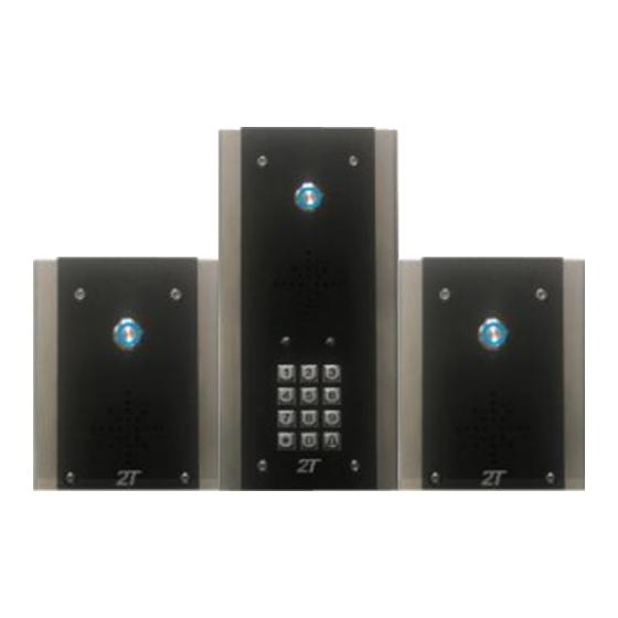
- Page 1 Voyager Voice - Sleek Model 2G & 3G Intercom system Installation & User Manual Scan the QR code and watch the installation video.
-
Page 2: Table Of Contents
Contents Before Installation ..................3 Pillar or Wall Mounting the Intercom ............4 Wiring of the Intercom ................5 Powering Up ..................... 6 Getting The Intercom Setup App .............. 9 Starting with The App ................ 10 Setting Call In and Call Out Phone Numbers ........11 Using The Intercom ................ -
Page 3: Before Installation
For this and other reasons we strongly recommend the use of a Bill Pay contract SIM with this intercom. Please contact your distributor or 2T Technology at sales@2t-tec.com to get details on our cost competitive Bill Pay SIM. -
Page 4: Pillar Or Wall Mounting The Intercom
Power A) Please use the power supply provided with the device B) Please place the power supply within a meter or two of the device. Long runs of narrow cable will cause problems. C) For longer runs of power cable between the power supply and the device Up to 2 meters - Use minimum 0.5mm (20 gauge) -
Page 5: Wiring Of The Intercom
Now wire the Power Supply and relay output to the terminals on the PCB as described in the diagrams that follow. Wiring of the Intercom Overview of the main GSM PCB The Diagram below shows the key connection points on the GSM Intercom PCB. -
Page 6: Powering Up
Wiring to the PCB 1. Output connection example Main PCB Output 2 Output 1 Relay 2 Relay 1 Gate Controller NO COM NC NO COM NC Keypad or Push Button Exit Device 12V DC Separate PSU Keypad or Magnetic Push button Lock Exit device Powering Up... - Page 7 2. Apply power to the GSM unit. The device will ask you to wait. Initially the Register light will be on constant and as the unit registers on the network, will start to flash every 1 second. 3. Give the Unit about 2 minutes to register when first turned on. When the Signal Strength light is on constantly or flashing the unit has signal from the network.
- Page 8 So that the unit can send itself a text message to synchronise the time of day it needs to know its own phone number. A) Get the telephone number from the SIM card that you have taken the SIM for the unit from. B) Program this into the GSM device as follows.
-
Page 9: Getting The Intercom Setup App
Please Note: Having set the SIM number in the device at step 5. In the last section, the device can now send itself an SMS text on powering up to synchronise its internal clock. This will be heard as a second Beep- Beep when this text is received by the GSM device. -
Page 10: Starting With The App
Starting with The App This section covers some of the main points of interest when using the Phone App for programming the GSM Intercom. We will cover five sections here which should give an overview of what can be done, but there are many other items that can be configured with the Phone App. -
Page 11: Setting Call In And Call Out Phone Numbers
Setting Call In and Call Out Phone Numbers Setup for Incoming Calls The GSM unit defaults to open access. With no programmed Open Telephone numbers any caller can open the gate or door. The GSM device sees the incoming call and hangs up the call. The GSM unit will pulse the Relay. -
Page 12: Using The Intercom
Using The Intercom With at least one ‘Call Out’ Phone number programmed, the device can be tested to place a call to this programmed phone number. Place the first Outgoing Call To test calling operation and audio quality you will need a second person either at the intercom or at the mobile phone. -
Page 13: Out Of Hours Setup (Do Not Disturb)
Out Of Hours Setup (Do Not Disturb) Out of Hours or Do Not Disturb mode ensures that calls can not be made from the GSM Intercom outside of certain times or even on certain days. First step is to enable this mode of operation with “OOH Mode On”... -
Page 14: Keypad Codes
Keypad Codes Keypad codes are 4 digits and can be setup as standard 24/7 codes, or as time and day limited codes, and even as temporary codes with a limited lifetime. This screen allows for the setup of a standard 24/7, 4 digit Keypad code which can always be used and lasts forever. -
Page 15: Automatic Schedules
Automatic Schedules Automatic schedules allow for the automatic opening and closing of gates or doors at pre set days and times. ** Use I button for info on this screen Select whether we want to set a schedule for Output 1 or Output 2. Set up the Schedule that we want to create for this Output. -
Page 16: Configure Input 1 And Input 2 For Open & Close Status
Configure Input 1 and Input 2 for Open & Close Status. Main PCB 2 INPUTS Contacts Or Limit Switch to determine gate open or closed Connect to Input 1 or Input 2. Input 1 allows the status to be queried. Input 2 will send a text on every activation. -
Page 17: Set Ring And Talk Time For Outgoing Calls
The message will go to the number programmed in Phone 1, unless the Control Phone is programmed (See section on ‘Program the Control Phone’ in the next section). In which case the message will go to the Control Phone. Now when the gate or door is opened the number will receive the “Access open”... -
Page 18: Options For Security Settings
** For these text commands to become active the device must be power cycled or the text command Reset can be sent to the device to restart it. Options for Security Settings A security code can be enabled for this device. Once enabled every text message must have the security code at the end of the text command. -
Page 19: Diagnostics
Diagnostics Diagnosing Problems When On Site the following tools can be used to diagnose problems with this system. LEDs on the PCB Tones and activity from the Phone Network, when calling the device. Red LED System Status indication Diagnostic SMS Text Response When remote from the site the following tools can be used to diagnose problems with this system. - Page 20 For Diag stored and Diag Live, a typical response to these commands is as follows: VME-IK 1 NV: SS too low: 5 Not checking SS: 0 Cant register: 0 OS Problem: 0 State stuck: 1 The Details of this response is given as follows: Returned Text Meaning VIME-IK 1 NV:...
-
Page 21: Red Led - System Health Status Indicator
RED LED - System Health Status Indicator Normally the Red LED is off. But by pressing the bell button on the keypad 4 times the red led will indicate the health status for the device. System Red LED Solution. State RED LED on Normal Wait for the device to leave this state. -
Page 22: Trouble Shooting Guide
Trouble Shooting Guide Question: I have powered up the unit. How will I know when it is ready to operate? Answer: 1. The first time the unit powers up it will make a “Beep-Beep” noise when it has registered on the network. 2. - Page 23 3. Confirm the SIM in the device has credit and has been topped up in the last 2 months. Having credit on the SIM is not enough. A PAYG SIM must be topped up regularly. 4. Check the spelling and the format of the text, matches that described in this manual.
- Page 24 2. The Red LED gives the health of the system. Normally the Red led is off. But by pressing the bell button on the keypad 4 times the red led will indicate the health status for the device 3. This should be flashing every 4 seconds. So it skips two flashes of the green LED and then flashes.
- Page 25 Also keep the GSM antenna away from the 12V PSU being used to power the system. 2. Lower the audio gain settings of the microphone and speaker. In areas of poor signal coverage high gain settings will increase the feedback gain and increase the levels of any audio noise present on the network.
- Page 26 Register of Telephone Numbers Programmed into the GSM Device. Phone 1 Phone 2 Phone 3 Phone 4 Phone 5 Open 1 Open 2 Open 3 Open 4 Open 5 Open 6 Open 7 Open 8 Open 9 Open 10 Open 11 Open 12 Open 13 Open 14...
- Page 27 Register of Keypad codes Programmed into the GSM Device. Valid for X days Days Valid Times valid Keypad Code or all days between Permanent code 1 code 2 code 3 code 4 code 5 code 6 code 7 code 8 code 9 code 10...
- Page 28 Rev 1.3 http://www.2t-tec.com...
Need help?
Do you have a question about the Voyager Voice Sleek and is the answer not in the manual?
Questions and answers