Creo Medical 7-EMR-050 Instructions For Use Manual
Electrosurgical generator
Hide thumbs
Also See for 7-EMR-050:
- Instructions for use manual (29 pages) ,
- Instructions for use manual (391 pages)
Table of Contents
Advertisement
Quick Links
Instructions for Use
Electrosurgical Generator
CAUTION: Federal law restricts this device to sale by or on the order of a physician
Reference (model): 7-EMR-050. Language: English.
For use with Creo Medical accessories and surgical instruments only.
Explanations of symbols, wordings and definitions
Yellow symbol.
General Warning
This device generates
non-ionizing radiation.
Do not remove the cover.
Blue symbol. Consult
Accompanying
Documents
Defibrillator-Proof Type
CF Applied Part
Manufacturer
Date of Manufacture
Reference (model)
number
Serial number
UL Classification Mark
(applicable only if this is
on the generator rear
E464226
panel)
Mains inlet power supply
fuses
Do not use if package is damaged
Packaging contains one unit
Instrument can be broken or
damaged if not handled carefully
Keep away from sunlight
Keep dry
Temperature limitation
Humidity limitation
Atmospheric pressure limitation
Caution – Generator detected
fault or error when the red
indicator above this symbol is
illuminated
Do not dispose of the
Electrosurgical Generator in
normal waste
Page 1 of 35
Advertisement
Table of Contents

Related Manuals for Creo Medical 7-EMR-050


Summary of Contents for Creo Medical 7-EMR-050
- Page 1 Electrosurgical Generator CAUTION: Federal law restricts this device to sale by or on the order of a physician Reference (model): 7-EMR-050. Language: English. For use with Creo Medical accessories and surgical instruments only. Explanations of symbols, wordings and definitions Yellow symbol.
- Page 2 Explanations of symbols, wordings and definitions Equipotentiality CE marking for the generator 2797 Settings for cutting COAG Settings for coagulation function function Cutting Waveform Active Coagulation Waveform Active MRI Unsafe Output from the Electrosurgical Generator Transportation, this Storage, this symbol appears next symbol appears next to to the symbols indicating the symbols indicating...
-
Page 3: Indications And Contraindications
The Electrosurgical Generator is intended to provide radiofrequency (RF) electrosurgical energy for cutting and microwave energy (MW) for coagulation (hemostasis, cauterization) and ablation of soft tissue, and is for use only with appropriate Creo Medical Instruments and accessories Indications and Contraindications Indications for Use and Contraindications depend on the appropriate Creo Instrument that is used with the Electrosurgical Generator. - Page 4 Use this Electrosurgical Generator only with appropriate Creo Instruments, Interface Cables and footswitch specified for use with this Electrosurgical Generator. Use of non-Creo Medical instruments and accessories may lead to unintended clinical effects with risk of injury or death to the patient.
-
Page 5: Safety Instructions
Do not open the cover of the Electrosurgical Generator or modify hardware or software in any way. Servicing of the Electrosurgical Generator must only be performed by Creo Medical Ltd personnel or their designated representative. Page 5 of 35... - Page 6 Safety Instructions Modification or opening of the Electrosurgical Generator by unqualified persons may result in electrical shock and will violate the warranty of the Electrosurgical Generator. In the event of failure of the Electrosurgical Generator, there is a risk of undesirable rise in output power that might cause unintended tissue effects.
- Page 7 Safety Instructions The Electrosurgical Generator contains no user serviceable parts. To avoid risk of electric shock and equipment malfunction do not remove any cover. Modification or opening of the generator by unqualified persons may result in electrical shock and will breach warranty of the generator. Microwave energy should be not be applied to persons wearing metallic jewelry or clothing containing metallic material.
-
Page 8: Rear Panel
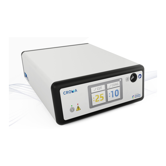
Device Description Front Panel On / Standby Button and LED Cut indicator LED (yellow) Warning indicator Coagulation indicator LED (blue) Symbol: Consult Accompanying Microwave indicator LED (flashing blue) Documents Symbol Defibrillation-proof type CF applied + / - Control Buttons part Menu control button Output connection socket Display... -
Page 9: Device Description
Device Description The Electrosurgical Generator comprises: - Mains-powered electrosurgical unit intended for operating theatre and endoscopy suite use. - Output: • Bipolar RF power at 400 kHz at up to 200 W • Microwave power at 5.8 GHz up to 62 W. •... - Page 10 Set-up Warning The Electrosurgical Generator must always be connected to an AC power supply with a protective ground (earth). Do not connect the power supply cord (also referred to as an AC power cord) if it appears damaged or contaminated, if it has been modified, or if it does not meet the requirement specified in the product specification table in this Instructions for Use, as there is a risk of electrical shock to the patient or user.
- Page 11 Set-up The Electrosurgical Generator should be positioned on a flat, horizontal worktop or suitable trolley such that the Front Panel is visible, and the Display STEP 1. are easy to read; controls are readily accessible; and Instruments can be connected for their intended use The Electrosurgical Generator should always be positioned so that it is possible to switch the unit off by using the On / Off Power switch (10) on the STEP 2.
-
Page 12: Normal Use
The Electrosurgical Generator continues to perform a series of internal STEP 3. self-checks while a screen is being displayed identifying Creo Medical Electrosurgical Generator and the selected language. When the self-checks are successfully completed, the message “Attach STEP 4. - Page 13 Normal Use Connecting the Instrument Warning Do not use the Interface Cable beyond its specified lifetime as specified in the Instruction for Use of the Interface Cable. The performance of the Interface Cable degrades if used after its specified lifetime which may result in unintended tissue effect.
- Page 14 Normal Use Connect the required Instrument to the Interface cable. Select and Confirm Connected Instrument Warning Ensure the correct Instrument is chosen from the options displayed by the generator. The wrong choice may result in serious injury to the patient and damage to the connected instrument.
- Page 15 Normal Use Treatment Screens The Treatment Screen appears on the display when the Instrument has been confirmed. There are two types of instrument treatment screens as shown in the below examples: In all Instrument examples the top line of the Treatment Screen displays the identity of the Instrument.
- Page 16 Normal Use Adjusting Power Outputs – Using the Footswitch Pedals Press and hold the footswitch Menu Button (the round button in the center of STEP 1 the footswitch) until the speaker of the Electrosurgical Generator sounds an audible acknowledgement; then release the button that was applied. The Electrosurgical Generator Display will then highlight the cut and/or coagulation STEP 2...
- Page 17 Normal Use Adjusting the Power Outputs – Using the Generator Buttons Press and hold the generator Menu Button (the button on the bottom left hand side of the display) until the speaker of the Electrosurgical Generator STEP 1 sounds an audible acknowledgement; then release the button that was applied.
- Page 18 Normal Use Activating the Power Output When the Treatment Screen is displayed, press the Left (yellow) footswitch to activate cutting energy subject to cutting being available from the Instrument type. Press the Right (blue) footswitch to activate coagulation energy. Confirm that the Electrosurgical Generator output settings are as intended before treating the patient.
- Page 19 Additional Settings Change Speaker Volume and Screen Brightness Caution Ensure the tones are audible over the typical background noises. To enable the adjustment of the Speaker Volume and Display Screen Brightness, press and hold the Front Panel Menu button (5) until the Electrosurgical Generator sounds an audible acknowledgement, then release the Menu button.
-
Page 20: Change Language
Use the + and – Control Buttons located on the left of the Front Panel to highlight the applicable language. When the required language is highlighted, confirm by pressing the Menu button The Electrosurgical Generator will then restart in the selected language. Creo Medical Ltd Electrosurgical Generator Software Version: VX.YZ EN DE FR IT ES NE Please note that the software version displayed generator may be different from the illustration above. - Page 21 70/30 Isopropyl Alcohol (IPA)/Water mix. In the event of any damage or degradation occurring to the Electrosurgical Generator as a result of cleaning, please contact Creo Medical immediately for advice. Do not use the Electrosurgical Generator when it appears to be damaged.
-
Page 22: Troubleshooting
Trouble Shooting The Electrosurgical Generator automatically performs a series of self- checks of its electronic circuits immediately when it is powered on, but before entering Standby mode. Additionally, treatment RF and microwave output checks are performed when the Electrosurgical Generator is switched ON from Standby. During activation of the RF and microwave outputs, further checks are performed to ensure that the output is as intended and as indicated to the user through the Display. - Page 23 • If the error condition persists, replace the Interface Cable • If replacing the Instrument and the Interface Cable does not correct the error condition, then the Electrosurgical Generator is most likely to be faulty. Contact Creo Medical. Applicable only when using a single energy type instrument, for Message: example, HS1 that uses the Coag output only.
- Page 24 ON / Standby Button to allow completion of not listed above system self-checks. Contact Creo Medical if the error persists and report the error or fault message and any error code that is also displayed. Page 24 of 35...
- Page 25 Specifications Product Specification Table Classification Under IEC 60601-1 Concerning Electrical Protection - Classification: Class 1. A protective earth connection must be provided Equipotential Terminal: According to IEC 60601-1 clause 8.6.7 Applied Part - Classification to IEC 60601:2005: Type CF. This is Defibrillator Proof. Ambient Temperature: +10 °C to +30 °C (+50 °F to +86 °F) Environment for...
- Page 26 Output Frequency: 396.7 kHz +/-2.0 kHz Power Capability: 35 W (Max) Output, RF (Treatment Rated Load: 400 Ohm Mode): Recommended Duty Cycle: 10 s ON, 30 s OFF, 1 hour RF Crest Factor: 1.6 continuous to 3.7 pulsed Maximum Voltage: 460 V peak Power Capability: 5,800 MHz +/- 1 MHz...
- Page 27 Specifications RF output load curves CUT Waveforms RS2 RF CUT Output Power Load Curve 1000 Tip Impedance (Ohms) CUT 15 CUT 20 CUT 25 CUT 30 CUT 35 Peak Voltage (V) Versus Waveform and Treatment Setting CUT 15 CUT 20 CUT 25 CUT 30 CUT 35...
- Page 28 Specifications Microwave COAG Output Load Curves RS2, reference 7-RS2-001 RS2 COAG Microwave Output Power Settings RS2 COAG Treatment Settings Nominal Fascia Peak Power Nominal Distal Power HS1, reference 7-HS1-001 HS1 COAG Microwave Output Power Settings HS1 COAG Treatment Setting Nominal Fascia Peak Power Nominal Distal Power Page 28 of 35...
- Page 29 Portable RF communications equipment (including peripherals such as antenna cables and external antennas) should be used no closer than 30 cm (12 inches) to any part of the Electrosurgical System (model ref 7-EMR-050) including cables specified by the manufacturer. Otherwise, degradation of the performance of this equipment could result.
-
Page 30: Specifications
Specifications Emissions EN 55011, Level A Group 2 in non-treatment modes. Blue Pedal Activation - Group 2 (deliberate generation in 5.8 GHz ISM band). Conducted Emissions: Exceeds EN 55011 Level A during RF (400 kHz) activation of the treatment output. Exemption from compliance with EN55011 is in accordance with EN60601-2-2. - Page 31 Specifications Guidance and Manufacturer’s Declaration – Electromagnetic Immunity The Electrosurgical Generator is intended for use in the electromagnetic environment specified below. The customer or the user of the Electrosurgical Generator should ensure that it is used in such an environment. IEC 60601-1-2 Test Electromagnetic Environment –...
- Page 32 Specifications Guidance and Manufacturer’s Declaration – Electromagnetic Immunity The Electrosurgical Generator is intended for use in the electromagnetic environment specified below. The customer or the user of the Electrosurgical Generator should ensure that it is used in such an environment. Compliance Immunity Test IEC 60601-1-2 Test Level...
- Page 33 Specifications Recommended Separation Distances between Portable and Mobile RF Communications Equipment and the Electrosurgical Generator The Electrosurgical Generator is intended for use in an electromagnetic environment in which radiated RF disturbances are controlled. The customer or the user of the Electrosurgical Generator can help prevent electromagnetic interference by maintaining a minimum distance between portable and mobile RF communications equipment (transmitters) and the Electrosurgical Generator as recommended below, according to the maximum output power of the communications equipment.
- Page 34 Footswitch: Creo Medical re-order product reference 7-PG1-132, marked Steute MKF 2 1S1S- MED GP26 For use only with Creo Medical surgical instruments and connection cables as follows: Surgical instrument HS1, reference 7-HS1-001 Surgical instrument ‘Speedboat’ RS2, reference 7-RS2-001 Connection cable procedure pack, reference 7-RS2-210 Environment for hospital/clinic storage prior to use and between uses Store at room temperature in a clean and dry environment out of direct sunlight.
- Page 35 Specification section of these Instructions for Use. In the event of product failure please contact Creo Medical Ltd to arrange servicing or repair. Please do not send the product to Creo Medical Ltd (or its authorized agent) without first obtaining a Returned Merchandise Authorization (RMA) number.
Need help?
Do you have a question about the 7-EMR-050 and is the answer not in the manual?
Questions and answers