
Summary of Contents for KNX Module PS-S.640.30.1
- Page 1 KNX POWER SUPPLY PS-S.640.30.1 User Manual Application Program: ver. 1.0 User Manual: ver. 1.0 module-electronic.ru...
-
Page 2: Table Of Contents
2.5 KNX bus reset function ........ -
Page 3: Basic Information
1 BASIC INFORMATION Intelligent power supply for the KNX system with an additional auxiliary power output of 29V DC, with the function of diagnostics of voltage in the KNX bus and protective against short circuit and overload. • Compact housing (2TE) •... -
Page 4: Specification
TP-256 Available application so ware ETS 4 and later KNX connector 4-wire EIB connector (PUSH WIRE spring clips) for standard cable TP1 0,8мм Ø KNX physical address by default 12.12.255 Operation temperature -5°C ... + 45°C Operation humidity 5 ... 95% (no condensation) -
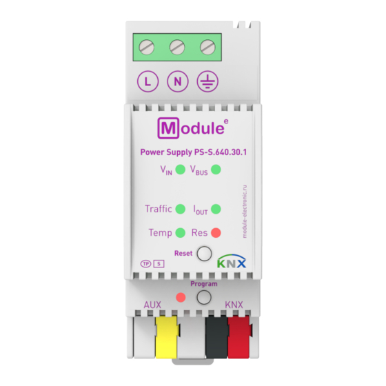
Page 5: Appearance
1. LED input voltage V 2. LED bus voltage V 3. LED telegram traffic 4. LED output current I 5. LED internal temperature 6. LED KNX reset 7. Programming LED Green: Input voltage is 195...265V AC 1. Input voltage V Red: Input voltage is out of this range Green: KNX bus voltage 28...31V DC... -
Page 6: Installation And Connection
Removing from DIN rail WIRING DIAGRAMS KNX bus ATTENTION! Installation and connection of the device to the mains must only be carried out by qualified personnel! There is a risk of electric shock! Be sure to turn off the power before installing or removing the device! Even when the device is turned off, the output... -
Page 7: Operational Description
Number and duration of overloads are stored. The same applies for the number of short circuits, device startups, KNX bus resets and for the duration of load detachments. The total operating time of the device and its operating time since last device startup are stored, too. Threshold values can be set for the bus voltage (only in the additional alarms), total current, telegram traffic and internal device temperature. -
Page 8: Event Counters
Number of short circuits and duration of load detachment are available details. The same applies for the number of KNX bus resets and of device startups, and for operating times. Additional alarms also provide the number of a value being in the threshold range and the duration of such event. -
Page 9: Parameter Structure For Measurement Sources
2.3 PARAMETER STRUCTURE FOR MEASUREMENT SOURCES On enabling a measurement source in the ETS tab «Measurements», the following parameter structure is available (exception: counters). An actual value can be sent over the bus a er a certain value change («Sending difference») or a er a pre-set time period has elapsed («Cyclic sending»). A value reaching the excess threshold range can be used to send telegrams containing «1»... -
Page 10: Individual Address Assignment
2.4.2 INDIVIDUAL ADDRESS ASSIGNMENT To configure the device an interface connection (IP, USB) to the KNX bus system is required. The device is supplied with the Individual Address 12.12.255. The KNX product database entry (available for ETS4 and higher) can be downloaded from the website and from the KNX Online Catalog. -
Page 11: Knx Bus Reset Function
During a bus reset, the device disconnects the entire bus line from the supplying output and induces a short circuit for 20 seconds. LED 6 (KNX Bus Reset) lights up red and goes off a er the reset process is accomplished. -
Page 12: Ets Database Parameters
3 ETS DATABASE PARAMETERS All screen shots are related to the PS-S.640.30.1 database file R1-1b in ETS5. Figure 2. Parameter tabs In the «General» tab the heartbeat period, the remote reset type (reset with «0» or with «1») and the delay of messages a er startup can be configured. -
Page 13: General
«Heartbeat» the device periodically sends out a telegram with «1». With use of the communication object no.36 «Power supply is on» the device sends out a telegram with «1» a er a KNX bus reset, a device startup and a short circuit. A er returning to normal working condition during the time delay no telegrams are sent. -
Page 14: Measurements
3.2 MEASUREMENTS The «Measurements» tab contains the menus «Output voltage», «Output current» and «Device temperature». The excess threshold range of the «Output voltage» is fixed and located outside the working range (28-31V). For example, with no «Output voltage» hysteresis the «Behaviour on alarm deactivation»... - Page 15 Setting ETS Parameter Comment {Factory Default} Output voltage disable; enable Enable/disable group associations, measurement Output voltage [V] {disable} and following settings 2-byte (DPT9); 4-byte (DPT14) Object type Select datapoint type {4-byte (DPT14)} disabled; 1min; 2min…5min; 10min; Cyclic sending Info telegram is sent regularly 15min…30min;...
- Page 16 «Alarm 1,2,3,4" tabs like described in chapter 3.7 . The «Output voltage» value is valid only if most of the loads is on the KNX bus output If the «Output current» value is < 10 mA, for calculations, the input voltage is assumed to be at 230 V module-electronic.ru...
-
Page 17: Maximum Tracking
3.3 MAXIMUM TRACKING With setting the «Tracking period» a certain period of time is tracked in order to find the maximum observed value contained. A er each expired period this value can be sent over the bus. The maximum tracking function is available for the measurement sources «Output current» and «Device Temperature». Figure 5. -
Page 18: Telegram Traffic
3.4 TELEGRAM TRAFFIC The «Telegram traffic» measurement source is similar to the measurement sources in the ETS tab «Measurements». The excess threshold range of the «Telegram traffic» is located only above its working range. Figure 6. Telegram traffic tab parameters Setting ETS Parameter Comment... - Page 19 Setting ETS Parameter Comment {Factory Default} disabled; Behaviour on alarm send value 0; send value 1; set Select action on leaving the threshold deactivation value to 0; set value to 1 (+hysteresis) range [send value 0] Table 7. Telegram traffic tab parameter settings module-electronic.ru page 19...
-
Page 20: Error Counters
3.5 ERROR COUNTERS The «Error Counters» tab contains the menus «Overload number counter», «Overload time counter», «Short circuits number counter» and «Load detached time counter». Activation of the parameters also activates the related communication objects. Info telegrams containing actual values can be sent regularly or according to a pre-set value difference. - Page 21 Setting ETS Parameter Comment {Factory Default} Overload time counter disable; enable Enable/disable group associations, time counter Duration of overloads [s] {disable} and following setting 0…32,000[s] Difference between actual and last sent value Sending difference {0} (= disabled) which triggers the sending Short circuit number counter disable;...
-
Page 22: Operational Counters
3.6 OPERATIONAL COUNTERS The «Operational counters» tab contains the menus «KNX bus reset number counter», «Device startup number counter», «Total operating time» and «Operating time since last device startup». Activation of the parameters also activates the related communication objects. Info telegrams containing the actual number counter value can be sent regularly. - Page 23 Setting ETS Parameter Comment {Factory Default} Device startup number counter disable; enable Enable/disable group associations, measurement Number of device startups {disable} and following setting disabled; 1min; 2min…5min; 10min; Cyclic sending Info telegram is sent regularly 15min…30min; 1h; 2h…8h {disabled} Total operating time disable;...
-
Page 24: Alarm 1,2,3,4
3.7 ALARM 1,2,3,4 A er enabling the alarm function the measurement source can be chosen. With the menu item «Alarmtype» the threshold range can be set. The alarm activation/deactivation can also be used to switch other devices. With the additional alarms 1-4, durations and numbers of threshold events can be sent on the bus. - Page 25 Setting ETS Parameter Comment {Factory Default} disabled; Behaviour on alarm send value 0; send value 1; set Select action on entering the threshold region activation value to 0; set value to 1 {send value 1} disabled; Behaviour on alarm send value 0; send value 1; set Select action on leaving the threshold deactivation value to 0;...
-
Page 26: Communication Objects
4 COMMUNICATION OBJECTS № Name Function Description Lenght With «Cyclic sending» the Send Output device sends the measured 2 bytes DPT9, measured voltage output voltage value in V 4 bytes DPT14 value (or mV). With the measured value entering the threshold range a Output Send telegram with value 0 or 1 is... - Page 27 1 bit a reset process. With «Cyclic sending» the Send KNX bus reset device sends the number counter 2 bytes number counter value of KNX bus value resets. With «Sending difference» the Total Send device sends the time counter operating counter...
- Page 28 № Name Function Description Lenght With «Sending difference» and «Cyclic sending» the device Send sends the number counter Counter 1 counter value (in s) indicating the 2 bytes value number of threshold events (for output current, output voltage, temperature). With the measured value entering the threshold range a Send telegram with value 0 or 1 is...
- Page 29 № Name Function Description Lenght With «Sending difference» the device sends the time counter Send value (in s) of a pre-selected Duration 4 counter 4 bytes variable (output current, value output voltage, temperature) being in the threshold range. With «Sending difference» and «Cyclic sending»...
-
Page 30: State Of Delivery
5 STATE OF DELIVERY 5.1 DEFAULT FACTORY SETTING General Individual address 12.12.255 Heartbeat 60 s module-electronic.ru page 30...