Table of Contents
Advertisement
Advertisement
Table of Contents

Summary of Contents for Heska element COAG+
- Page 1 Veterinary Analyzer Product Manual...
-
Page 2: Table Of Contents
Table of Contents Section 1: Introduction ............1 1.1 Before Starting ..............1 1.2 Intended Use ..............1 1.3 Test Principle ..............1 1.4 Packaging ...............1 Section 2: Product Overview ..........2 Section 3: Operation Summary ......... 4 Section 4: Before Testing ........... 4 Section 5: Precautions, Limitations and Warnings .. - Page 3 7.7 Operator ID ..............21 Section 8: Sample Test ............ 24 8.1 Choosing Test Type ............24 8.2 Input Sample No............24 8.3 Insert Test Strip .............25 8.4 Input Test Strip Information ...........25 8.5 Install Codechip ............26 8.6 Heating .................27 8.7 Add Sample ..............28 8.8 Collecting a Sample ............28 8.9 Peforming the Test ............28 8.10 Test Results ..............29...
- Page 4 Section 11: Maintenance ..........41 11.1 Screen Care and Cleaning .........41 11.2 Precautions for Lithium-Ion Battery ......43 11.3 Servicing ..............43 Section 12: Troubleshooting ........... 44 Section 13: Symbols ............48 Section 14: Operating Conditions and Product Specifications ..............49 14.1 Operating Conditions ..........49 14.2 Product Specifications ..........49 Section 15: Special Storage Conditions &...
-
Page 5: Section 1: Introduction
If you find any damage that may be caused by transportation, please inform Heska's Technical Support Services. Please pay attention to content where the symbol “ ” appears in the... -
Page 6: Section 2: Product Overview
2. Product Overview Front View 1. Test Strip Guide 2. Touchscreen Back View 3. Footpad 4. Battery Cover with Label 5. Magnetic Charging Port... - Page 7 Left View Right View 6. Power Button 7. Codechip Strip Slot Top View 8. Micro USB Data Port 9. DC 5V Power Supply Jack...
-
Page 8: Section 3: Operation Summary
3. Operation Summary Operation Preparation Sample No. Reference aPTT Units Language PT Units WIFI Switch Codechip Range Setting Setting Setting Setting Setting Meter Setup Transport Date/Time Beeper Backlight Screen Sleep Upload Operator ID Mode Setting Setting Setting Rotation Setting Setting Insert Input Test Insert... -
Page 9: Section 5: Precautions, Limitations And Warnings
5.1 Element COAG+™ Analyzer Care ● DO NOT spill any liquid on the Element COAG+ Analyzer. In this case, immediately contact Heska’s Technical Support Services. ● The Element COAG+ Analyzer is a delicate instrument and should be handled with care. Dropping or mishandling may cause malfunction of Element COAG+ Analyzer. -
Page 10: Patient Health Status
● Do not use this instrument near cellular or cordless telephones, walkie talkies, garage door openers, radio transmitters, or other electrical or electronic equipment that are sources of electromagnetic radiation, as these may interfere with the proper operation of the instrument. 5.3 Patient Health Status Current patient health status may cause inaccurate or unexpected test results. -
Page 11: Warning Information On Built-In Lithium Battery
● The user must use the matching 5V special charger provided by Heska to charge. ● Do not bring the analyzer close to a high-temperature heat source. ● Do not allow the analyzer to be hit or exert heavy pressure on the analyzer. -
Page 12: Section 6: Power On/Off
6. Power ON/OFF 6.1 Battery and Charging When turning on the analyzer for the first time after unpacking, please connect the adapter for power supply and turn off the transportation mode. You do not need to repeat this operation for subsequent reboot. Ensure the analyzer is fully charged (Approximately 3.5 hours to fully charge) before using for the first time. -
Page 13: Sleep Mode
Once Operator ID is On, the Log out icon in main screen will be enabled and displayed in teal (Figure 1-2). To switch between operators, please return to the screen for inputting the Operator ID by pressing the Log out icon, and then re-enter the Operator If Operator ID is Off, the Log Out icon on main screen will be disabled... -
Page 14: Power Off
6.4 Power OFF After depressing the Power button for 3 seconds, the system will deliver a message. Press " " to power off the instrument, or press " " to cancel the operation (Figure 1-4). When the battery power of the analyzer is exhausted, it will automatically shut down. -
Page 15: Language
7.2 Language Click "Language" from the Settings screen (Figure 2-1) to view and select a language (Figure 2-2). Click " " to return to the previous screen and click " " to return to the main menu. 7.3 WIFI WIFI connectivity allows the analyzer to connect with Practice Information Management Software (PIMS) and can be used for data transmission. - Page 16 The system will search for nearby hotspots and list automatically. Click the hotspot name to enter the password to connect successfully. The system will remember the password and connect to the last connected hotspot automatically. The server is used for wireless data transmission with the specific Practice Information Management Software.
-
Page 17: Test Parameter
7.4 Test Parameter Click "Test Parameter" from the Settings screen (Figure 2-1) to set the parameters (Figure 2-6). 7.4.1 Sample No. From the Test Parameter screen (Figure 2-6), click Sample No. to set the Sample number (Figure 2-7). If the Sample No. button is grayed out, then the sample does not need to be numbered. - Page 18 Click “Test Strip” from Codechip menu (Figure 2-8) to enter Test Strip menu (Figure 2-9). The Codechip information of the installed strip is displayed in this menu. A new strip Codechip can also be installed by inserting the strip Codechip into the Codechip slot (See the right figure in Section 2 Product Overview).
- Page 19 In addition to the Codechip menu, a Codechip can be installed during the test. When testing with a test strip or control, and an installed Codechip, the installation operation is no longer required during the test; otherwise, the system enters the prompt menu which enables the user to install the desired Codechip accordingly.
- Page 20 Click any value in the Reference Range table to automatically enter the menu which allows the user to modify the value, and the user can re-modify the upper and lower limits (Figure 2-12) within the given setting range. After the value range is modified, if the test result is below the lower limit, a popup will prompt, "Illegal Input".
-
Page 21: System Parameter
7.5 System Parameter Click "System Parameter" from the Settings screen (Figure 2-1) to enter the screen (Figure 2-15) that prompts the user to set the system parameters. Click " " to return to the previous screen and click " " to return to the main menu. - Page 22 7.5.2 Beeper Click "Beeper" from the System Parameter screen (Figure 2-15) to enter the screen (Figure 2-17) that prompts the user to set the beeper. The beeper is turned off when the Beeper button is grayed out. The beeper is turned on when the Beeper button is teal, and the user can set different volumes: high, medium and low.
- Page 23 7.5.4 Brightness Adjustment Click "Brightness" from the System Parameter screen (Figure 2-15) to enter the brightness adjustment screen (Figure 2-19). The adjustment range is between 1 and 10. Click " " to return to the previous screen and click " "...
- Page 24 7.5.6 Auto Upload Click "Auto Print/Upload" from the System Parameter screen (Figure 2-15) to enter the print/upload setting screen (Figure 2-21). The Auto Upload function is disabled when the button is grayed out. The Auto Upload function is enabled when the button is teal. Click " "...
-
Page 25: About The Device
7.6 About the Device Click "About the Device" from Settings screen (Figure 2-1) to enter the screen that displays the system information (Figure 2-23). The user can check the version and log information. Click " " to return to the previous screen and click " "... - Page 26 After touching "User Management" from the Operator ID screen (Figure 2-24), the administrator can enter the screen and view the created user list (Figure 2-25). To create a new user account, please touch " " at the bottom of the screen. The number of user accounts should not exceed 50.
- Page 27 (Figure 2-27). If a user forgets their password, contact the administrator to reset the user password. If the administrator forgets the password, please contact Heska's Technical Support Services. 2-27 The user can log in to any existing account from the Login screen.
-
Page 28: Section 8: Sample Test
8. Sample Test 8.1 Choosing Test Type In the Test Type interface, select the test type. The available test types include: cat, dog and other. Click " " to return to the previous screen and click " " to return to the main menu. -
Page 29: Insert Test Strip
8.3 Insert Test Strip Once the Insert a Test Strip screen appears on the analyzer, insert the test strip in the direction shown (Figure 3-3). Keep inserting the strip as directed until the sample well is aligned with the dot on the instrument. -
Page 30: Install Codechip
Angle: The light field should be as perpendicular to the barcode plane as possible, and the vertical deviation should have the highest recognition rate within ±5°. 8.5 Install Codechip Insert the test strip Codechip into the chip slot (see Section 1.3 for position details), then the specific Codechip information will display (Figure 3-5). -
Page 31: Heating
When the input Codechip number of the test strip has expired, the system will deliver a warning message indicating that the Codechip has expired. 8.6 Heating After the test strip is inserted and its Codechip is installed, the instrument will enter the heating state, and the screen will display the heating progress (Figure 3-8). -
Page 32: Add Sample
8.7 Add Sample The system will count down and prompt the user to add sample upon the completion of heating (Figure 3-9). The sample must be added within 10 minutes. Do not move the instrument when adding the sample. If the sample is not added properly within 10 minutes, the system will deliver an error message indicating that sample... -
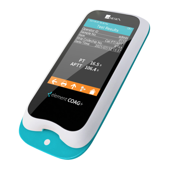
Page 33: Test Results
After the sample is added properly, the system will start the test automatically and display the test progress (Figure 3-10). Do not perform other operations on the analyzer during testing. 3-10 8.10 Test Results Please check the test strip insert for an explanation of the results. The system will display the test results after the test is completed (Figure 3-11). - Page 34 If the test strip has not been removed after the test is completed, please click " " from the test result screen to go to the strip removal screen (Figure 3-12), and remove the test strip in the direction shown in the figure.
-
Page 35: Section 9: Quality Control
9. Quality Control ● Onboard QC Test The Element COAG+ utilizes a number of internal quality methods to ensure proper operation. The built-in quality control of the instrument automatically monitors critical conditions before and during the testing period. The onboard quality control of the test strip detects the signal characteristics of two channels. -
Page 36: Input Test Strip Information
9.2 Input Test Strip Information After the test strip is inserted, please enter the Test Strip Information screen, and input the Codechip number of the test strip (Figure 4-2). The Codechip number can be manually entered and then click " "... - Page 37 When the entered Codechip number of the test strip does not match the Codechip information, the system will provide a warning message indicating that the Codechip information does not match. When the entered Codechip number of the test strip has expired, the system will provide a warning message indicating that the Codechip has expired.
-
Page 38: Input Qc Information
9.4 Input QC Information After the Codechip is installed, enter the Codechip number of the QC liquid (Figure 4-6). (See outer package for details.) The Codechip number can be entered manually and then click " " to save, or by scanning the barcode on the package of the test strip. -
Page 39: Heating
When the input Codechip number of QC liquid does not match the Codechip information, the system will provide a warning message indicating that the Codechip information does not match. When the input Codechip number of QC liquid has expired, the system will provide a warning message indicating that the Codechip has expired. -
Page 40: Add Sample
9.7 Add Sample The system will count down and prompt the user to add sample (Figure 4-11) upon the completion of heating. The sample must be added within 10 minutes. Please strictly follow the requirements of the QC liquid insert during sample adding. Do not move the instrument when adding sample. -
Page 41: Qc Test Results
9.9 QC Test Results The system will display the QC test results after the test is completed (Figure 4-13). The test results can be uploaded, provided that the instrument is properly connected to the server. 4-13 If the test strip has not been removed after the QC test is completed, please click "... -
Page 42: Section 10: Results
10. Results When the storage amount of the sample result reaches 80% of the total amount of the analyzer, the user will be prompted to upload data. If the user does not upload the data, the sample results will automatically overwrite the oldest records after the total amount exceeds the limit. -
Page 43: Test Results
10.2 Test Results Click "Test Results" from the Results screen (Figure 5-1) to enter the test results query screen (Figure 5-3). If there are multiple test results, please scroll through the display for all results. Click " " on the Test Results screen to clear all test results. -
Page 44: Qc Results
10.3 QC Results Click "QC Results" from the Results screen (Figure 5-1) to enter the QC Results query screen (Figure 5-5). If there are multiple QC test results, please scroll through the display to list all results. Click " " in the test results screen to clear all test results. -
Page 45: Section 11: Maintenance
11. Maintenance 11.1 Screen Care and Cleaning Follow these steps for cleaning the analyzer: 11.1.1 Cleaning Frequency 1. Clean the analyzer after every patient and when there are visible signs of soil and/or organic material prior to disinfecting. Also follow any facility disinfection SOPs. 2. - Page 46 Table 1. Recommended Cleaning Cloths Name Disinfectant Size PDI SaniCloth Quaternary/low–alcohol 8" x 14" or ® Plus formula (14.85% IPA). 6" x 6.75" Quaternary/low–alcohol 9" x 12" or ® CaviWipes formula (17.2% IPA). 6" x 6.75" 11.1.5 Cleaning and disinfecting the analyzer housing. 1.
-
Page 47: Precautions For Lithium-Ion Battery
11.2 Precautions for Lithium-Ion Battery Element COAG+ Analyzer has a built-in lithium-ion battery, which cannot be removed by any user. For battery replacement, please contact Heska's Technical Support Services. If you plan not to use the analyzer for more than one month, please fully charge the analyzer. -
Page 48: Section 12: Troubleshooting
12. Troubleshooting When you receive an error code, please retest. If you receive a second error code, then contact Heska's Technical Support Services and test the patient with a laboratory method. Do not interpret an error code as a patient result in any case. - Page 49 Description Corrective Actions Please turn off the analyzer and reboot. If the problem E008 Scanning error. recurs, please contact Heska's Technical Support Services. The operation of Make sure the sample adding is E010 sample adding has completed before the end of the timed out.
- Page 50 5 minutes, E019 analyzer is too high. then turn on the analyzer and restart the test. If the problem recurs, please contact Heska's Technical Support Services. Please retest with a new test strip. If the problem recurs, The coagulation...
- Page 51 Error Code Description Corrective Actions Please retest with a new test strip. If the problem recurs, PT result is above please contact Heska's E025 reportable range. Technical Support Services and use the laboratory method to perform the test. Please retest with a new test strip.
-
Page 52: Section 13: Symbols
13. Symbols Symbols Explanation Symbols Explanation Consult Instructions Expiry Date For Use Caution. Read Fragile Carefully Keep Dry Biological Risk Separate Collection Do Not Reuse Temperature Manufacturer Limitation Catalogue Number Serial Number Laser Radiation Risk Lot Number CE Marking... -
Page 53: Section 14: Operating Conditions And Product Specifications
14. Operating Conditions and Product Specifications 14.1 Operating Conditions Temperature 50ºF - 95ºF (10ºC - 35ºC) Humidity 10% - 90% (No condensation) Altitude 14,000 feet (4,300 m) 14.2 Product Specifications Processor 32–Bits V2 ARM Cortex–M4 Display 320 × 480 LCD Touch screen Capacitive touch screen QR code scanning module... -
Page 54: Section 15: Special Storage Conditions & Methods
©2021 Heska Corporation. CaviWipes is a registered trademark of Metrex Research LLC. Sani- Cloth is a registered trademark of Professional Disposables International, Inc. HESKA is a registered trademark and Element COAG+ is a trademark of Heska Corporation in the United States and other countries. US21MD0201...
Need help?
Do you have a question about the element COAG+ and is the answer not in the manual?
Questions and answers