Table of Contents
Advertisement
Quick Links
UM2502
User manual
STLINK-V3MODS and STLINK-V3MINI debugger/programmer
tiny probes for STM32 microcontrollers
Introduction
STLINK-V3MODS and STLINK-V3MINI are stand-alone debugging and programming tiny
probes for STM32 microcontrollers. These products are designed in a very low form factor
and both offer high performance without any compromise to functions. They support the
JTAG/SWD interfaces for communication with any STM32 microcontroller located on an
application board.
They provide a Virtual COM port interface allowing the host PC to communicate with the
target microcontroller through one UART. The STLINK-V3MODS also provides bridge
interfaces to several communication protocols allowing for instance the programming of the
target through the bootloader.
The STLINK-V3MODS and STLINK-V3MINI are both proposed for different uses. The
STLINK-V3MODS may be directly soldered on a host PCB including an STM32 application-
based with its 2 x 16-pin castellated vias connection, while the STLINK-V3MINI offers
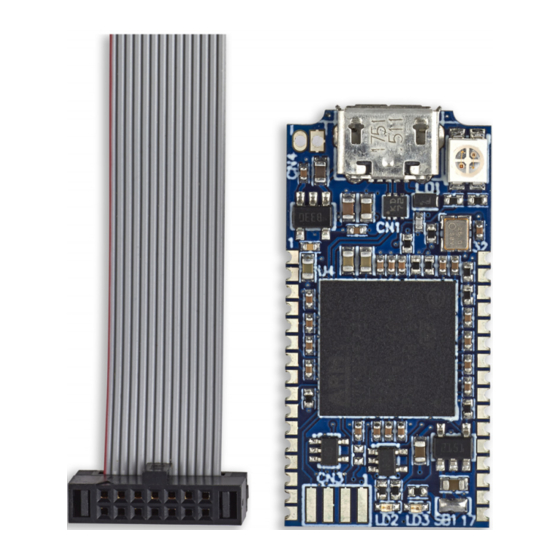
STDC14 connectivity with an included STDC14 to STDC14 flat cable.
Figure 1. STLINK-V3MODS product top view
Figure 2. STLINK-V3MINI product top view
Pictures are not contractual.
December 2021
UM2502 Rev 2
1/28
www.st.com
1
Advertisement
Table of Contents

Related Manuals for ST STLINK-V3MODS


Summary of Contents for ST STLINK-V3MODS
-
Page 1: Figure 1. Stlink-V3Mods Product Top View
The STLINK-V3MODS and STLINK-V3MINI are both proposed for different uses. The STLINK-V3MODS may be directly soldered on a host PCB including an STM32 application- based with its 2 x 16-pin castellated vias connection, while the STLINK-V3MINI offers STDC14 connectivity with an included STDC14 to STDC14 flat cable. -
Page 2: Table Of Contents
Mass storage interface ........15 5.5.5 Bridge functions (STLINK-V3MODS only) ..... . . 15 5.5.6 LEDs . - Page 3 Appendix A STLINK-V3MODS recommended land pattern ....22 Appendix B STLINK-V3MODS board dimensions ......23 Appendix C STLINK-V3MODS reference design for voltage adapter .
- Page 4 32-pin edge connector for STLINK-V3MODS ........
- Page 5 Figure 11. STLINK-V3MODS recommended land pattern ........22 Figure 12.
-
Page 6: Features
Virtual COM port (VCP) up to 16 Mbps • 3.0 to 3.6 V application voltage support and 5 V tolerant inputs STLINK-V3MODS features • Direct-to-PCB implementation by 2 x 16-pin 1.27mm edge castellated vias with all signals available in a minimum PCB required surface •... -
Page 7: Ordering Information
UM2502 Ordering information Ordering information To order the STLINK-V3MODS or STLINK-V3MINI tiny probe, refer to Table Table 1. Ordering information Content Order code Description Differentiating feature references STLINK-V3MODS – MB1467 – 2 x 16-pin castellated vias STLINK-V3 in-circuit debugger and programmer for STM32 –... -
Page 8: Development Environment
• Keil - MDK-ARM • STMicroelectronics - STM32CubeIDE Firmware upgrade The STLINK-V3MODS and STLINK-V3MINI tiny probes embed firmware which needs to be frequently updated from the www.st.com website to benefit from new functionality or corrections. Refer to the technical note Overview of ST-LINK derivatives (TN1235) for details. -
Page 9: Quick Start
Using STLINK-V3MODS requires to be firstly soldered onto the destination application including the targeted STM32 microcontroller. Some recommendations are given here: Reserve in the design the necessary PCB area under the STLINK-V3MODS by using the recommended PCB land pattern. Apply the recommended reflow soldering profile, from Soldering recommendations and... -
Page 10: Stlink-V3Mods And Stlink-V3Mini Functional Description
These modules are fully powered by the PC. If the COM LED blinks red, refer to the technical note Overview of ST-LINK derivatives (TN1235) for details. STLINK-V3MODS and STLINK-V3MINI frequency selection The STLINK-V3MODS and STLINK-V3MINI run internally at three different frequencies: • high-performance frequency •... -
Page 11: Figure 3. Stlink-V3Mini Connections
UM2502 STLINK-V3MODS and STLINK-V3MINI functional description Figure 3. STLINK-V3MINI connections connection application MSv61219V1 Figure 4. STLINK-V3MODS connections connection Host board MSv61220V1 For the STLINK-V3MODS, the connections are done with the host board by tracks. UM2502 Rev 2 11/28... -
Page 12: Hardware Layout
STLINK-V3MODS and STLINK-V3MINI functional description UM2502 Hardware layout The STLINK-V3MODS and STLINK-V3MINI products are designed around the STM32F723 microcontroller (176-pin in UFBGA package). Figure 5 shows the STLINK-V3MODS and Figure 6 the STLINK-V3MINI. Figure 7 Figure 8 show MB1467 top and bottom layouts which is the common board reference for STLINK-V3MODS and STLINK-V3MINI. -
Page 13: Figure 6. Hardware Board Stlink-V3Mini
UM2502 STLINK-V3MODS and STLINK-V3MINI functional description Figure 6. Hardware board STLINK-V3MINI Figure 7. MB1467 top layout USB Micro-B connector to PC Force reset (CN4) COM LED (LD1) 2 x 16-pin edge connector STM32F723 castellated vias microcontroller 5 V power LED... -
Page 14: Figure 8. Mb1467 Bottom Layout
STLINK-V3MODS and STLINK-V3MINI functional description UM2502 Figure 8. MB1467 bottom layout STDC14 connector (CN5) (STLINK-V3MINI only) MSv61224V2 Figure 9. MB1467 mechanical drawing (in millimeters) 14/28 UM2502 Rev 2... -
Page 15: Stlink-V3Mods And Stlink-V3Mini Functions
STM32 target Flash memory with drag-and-drop action of a binary file from a file explorer. This ability requires the STLINK-V3MODS or STLINK-V3MINI tiny probe to identify the connected target before enumerating it on the USB host. -
Page 16: Leds
ST bridge software interface. 5.5.6 LEDs Power LED: Red light indicates that 5 V is enabled. COM LED: Refer to the technical note Overview of ST-LINK derivatives (TN1235) for details. Fault LED: Indicates USB overcurrent request. 16/28 UM2502 Rev 2... -
Page 17: Board Connectors
Input only pin Output only pin Input/Output pin 6.1.1 USB Micro-B The CN5 USB connector is used to connect the embedded STLINK-V3MODS or STLINK- V3MINI to the PC. 6.1.2 32-pin edge connector for STLINK-V3MODS (STM32 JTAG/SWD, VCP and bridges) Table 3. 32-pin edge connector for STLINK-V3MODS... - Page 18 200 mA. Please notice that exceeding this maximum output current over 200 mA may damage the device or cause communication issues with the host PC (A PC standard USB connector cannot provide more than 500 mA by the USB port and STLINK-V3MODS can request dynamic current surges during target devices programming).
-
Page 19: Stdc14 For Stlink-V3Mini (Stm32 Jtag/Swd And Vcp)
UM2502 Board connectors 6.1.3 STDC14 for STLINK-V3MINI (STM32 JTAG/SWD and VCP) The CN5 STDC14 connector allows the connection to an STM32 target using the JTAG or SWD protocol, respecting (from pin 3 to pin 12) the ARM10 pinout (Arm Cortex Debug connector). -
Page 20: Product Information
Any consequences deriving from such usage will not be at ST charge. In no event, ST will be liable for any customer usage of these engineering sample tools as reference designs or in production. -
Page 21: Product Identification Lkv3Mini$At2
UM2502 Product information Product limitation No limitation identified for this product identification. 7.2.4 Product identification LKV3MINI$AT2 This product identification is based on the MB1467 revision B-02, where R3 is fitted on the board. Product limitation No limitation identified for this product identification. Board revision history 7.3.1 Board MB1467 revision B-01... -
Page 22: Appendix A Stlink-V3Mods Recommended Land Pattern
STLINK-V3MODS recommended land pattern UM2502 Appendix A STLINK-V3MODS recommended land pattern Figure 11. STLINK-V3MODS recommended land pattern PCB edge of the host board Do not place components in this area MB1467 3 mm min. 15.24 mm 22/28 UM2502 Rev 2... -
Page 23: Appendix Bstlink-V3Mods Board Dimensions
UM2502 STLINK-V3MODS board dimensions Appendix B STLINK-V3MODS board dimensions Figure 12. STLINK-V3MODS mechanical dimensions (in millimeters) 9.60 mm 2.82 mm 1.12 mm 15.24 mm MSv55156V1 UM2502 Rev 2 23/28... -
Page 24: Appendix Cstlink-V3Mods Reference Design For Voltage Adapter
STLINK-V3MODS reference design for voltage adapter A document describing how to connect a voltage adapter to the STLINK-V3MODS is available on the www.st.com/stlink-v3mods website under the CAD resources tab. This document is given as a guidance and reference design helping customers how to realize a 1.65 to 3.60 V voltage adapter to the STLINK-V3MODS compact in-circuit debugger and... -
Page 25: Statements
UM2502 Federal Communications Commission (FCC) and Innovation, Science and Economic De- Appendix D Federal Communications Commission (FCC) and Innovation, Science and Economic Development Canada (ISED) Compliance Statements FCC Compliance Statement Part 15.19 This device complies with Part 15 of the FCC Rules. Operation is subject to the following two conditions: (1) this device may not cause harmful interference, and (2) this device must accept any interference received, including interference that may cause undesired operation. - Page 26 Federal Communications Commission (FCC) and Innovation, Science and Economic Develop- interference, and (2) this device must accept any interference, including interference that may cause undesired operation of the device. ISED Canada ICES-003 Compliance Label: CAN ICES-3 (A)/NMB-3(A). Déclaration de conformité Avis: Le présent appareil est conforme aux CNR d'ISDE Canada applicables aux appareils radio exempts de licence.
-
Page 27: Revision History
V3MODS and STLINK-V3MINI functional description Added: – 5 V source output capability subsection – STLINK-V3MODS board dimensions with new Figure 12 – STLINK-V3MODS reference design for voltage 14-Dec-2021 adapter Updated: – Title, Features, Figure Figure Table 3 Table 4 –... - Page 28 ST products and/or to this document at any time without notice. Purchasers should obtain the latest relevant information on ST products before placing orders. ST products are sold pursuant to ST’s terms and conditions of sale in place at the time of order acknowledgement.
Need help?
Do you have a question about the STLINK-V3MODS and is the answer not in the manual?
Questions and answers