Table of Contents
Advertisement
Quick Links
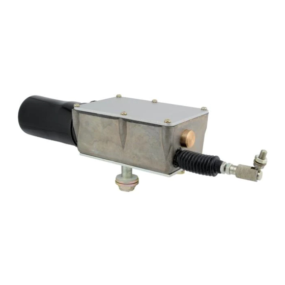
720 SERIES ACTUATOR – BASIC SETUP
1. Complete the wiring of the electrical system per the enclosed wiring
diagram (Actus drawing number 999-0172). Note the 3 Amp (slow
blow) breaker in the circuit. This is highly recommended as a standard
practice to protect the actuator from overload and failure. A slow blow
fuse is required because draw can reach 7 amps when stalled.
2. Before applying power, double check the following important areas:
a. Proper wiring technique is critical. All wires and cables should be
tied down and positioned so they will not be accidentally pulled
or knocked loose. All wiring subject to high wear or vibration
should be run through loom to protect from shorting to the
vehicle frame.
b. Double check all ground wires as shown on the wiring diagram.
All frame grounds should be free of corrosion, paint, and dirt.
Wires shown running direct to the negative post of the battery
should be attached there, or to a similar good direct ground.
Frame grounding is not recommended for these wires. Note that
this actuator is grounded with terminal #3. Terminals #4 and
#5 provide bi-directional motor control.
c. This is a negative ground, 12 or 24 VDC system. Be sure correct
power is applied and regulated.
d. Certain motor speeds require different wiring. Check the truth
table on the wiring diagram.
3. Mount actuator to device that is to be stroked. Check to make sure
mounting mechanism on the actuator matches mounting required to
stroke the lever. This is a linear actuator and will be damaged if it is
stroking a mechanism that is not moving in a straight linear motion.
This arcing motion requires the actuator to be mounted with the pivot
pin mounting bracket option. Also be sure to minimize side loads to
the actuator rod end.
090407AJN
Advertisement
Table of Contents
Troubleshooting

Summary of Contents for ACTUS 720 Series
- Page 1 720 SERIES ACTUATOR – BASIC SETUP 1. Complete the wiring of the electrical system per the enclosed wiring diagram (Actus drawing number 999-0172). Note the 3 Amp (slow blow) breaker in the circuit. This is highly recommended as a standard practice to protect the actuator from overload and failure.
- Page 2 4. Before connecting the linkage, run unit back and forth to make sure that the stroke of the actuator matches that of the lever to be moved. If the stroke of the actuator needs to be adjusted, proceed as follows: a.
- Page 3 720 SERIES ACTUATOR – TERMINAL BLOCK Here is the terminal block: 1. Take a small flat blade screw driver and insert it into the slot above where you want the wire to go. 2. Press down 3. As you continue to press down,...
- Page 4 In the event of failure or improper operation, please follow the steps outlined below. System Check Double check all wiring. Make sure you are using the Actus wiring diagram drawing number 999-0172. Proper wiring technique is critical. 90% of all field problems can be traced to a poor connection or improper wiring.
- Page 5 2000 ohms. If the actuator operates as described, proceed with step #12. If the pot does not operate properly, the P.C. board assembly can be replaced by ordering Actus part number 024- 0577. Motor Check 12.
- Page 6 15. If the actuator operates as described, the problem points to the limit switches. The switches can only be replaced by ordering a complete P.C. board. Actus part number 024-0576 (024-0577 – P.C. board with feedback pot). If the motor will not operate, it must be replaced.
- Page 7 720 Actuator Wiring Diagram 245 East Roselawn Ave, Suite 23 . St. Paul MN 55117 Main 651.487.8716 . Fax 651.487.4173 www.ACTUSINC.com...
Need help?
Do you have a question about the 720 Series and is the answer not in the manual?
Questions and answers