
Related Manuals for APtronic INV250-45EU RS485

Summary of Contents for APtronic INV250-45EU RS485
- Page 1 Micro-Inverter INV250-45EU RS485 INV250-45EU PLC INV250-45EU INV350-60EU RS485 INV350-60EU PLC INV350-60EU English...
- Page 2 Installation and Operation Manual for INV250-45EU RS485, INV250EU-45 PLC and INV250EU-45 INV350-60EU RS485, INV350EU-60 PLC and INV350EU-60 Printed in Germany, Copyright by APtronic AG...
-
Page 3: Table Of Contents
Table of Contents About this Manual Symbols used Scope Target Audience Safety and Regulations General Information and Safety Instructions 2.1.1 Storage, Transportation, Operation and Maintenance 2.1.2 Assembly, Installation and Electrical Connection CE Mark Label Notes on Liability, Warranty and Service Intended use and liability Guaranty and Warranty Service... -
Page 4: About This Manual
This manual applies to the following micro-inverters: - All contacts should be kept dry and clean! - Transport the inverter only in the given • INV250-45EU packaging. • INV250-45EU RS485 • INV250-45EU PLC • INV350-60EU 2.1.2 Assembly, Installation and Electrical Connection •... -
Page 5: Ce Mark
3.2 Guaranty and Warranty • Low Voltage Directive (Directive 2006/95/EC) (See page 19 for declaration of CE-Conformity) APtronic grants an implied warranty of 2 years to the inverter from date of purchase. Furthermore, APtronic provides an 2.3 Label additional limited warranty for several years. For warranty questions, please contact your retailer or installer. -
Page 6: Derating
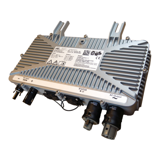
70°C and 1000 W/m² provide only a maximum of 164W. 5.0 Product Description The APtronic Micro-Inverter is individually connected to one or two PV-module, depending on technical specifications, and converts the direct current into grid compliant alternating current. Through the individual conversion at each module, the sun’s energy can ideally be used. -
Page 7: Led-Display
The following monitoring concepts and protection plans are provided that the input voltage is within the acceptable range. included in the APtronic scope of devices: It may happen that the inverter switches off for safety reasons, if •... -
Page 8: Installation
8.1 Connections Overview To find the optimal location for the inverter, a summary of key The connections of the APtronic Micro-Inverter are described below. criteria that should be considered is listed below. Select an installation location so that the following points will 8.1.1 Connections of PLC and NoCom Devices... -
Page 9: Ac-Connection Of Plc And Nocom Devices
8.2 AC-Connection 8.2.1 AC-Connection of PLC and NoCom Devices The layout of the AC connection depends on the version of the micro-inverter. For both versions the following applies: Connect the inverters using the AC wiring from one inverter to the next, in ways that are further explained for each version in the following sections. -
Page 10: Dc-Connection
When disconnecting the cable couplings press the mounting 8.3 DC-Connection link together by hand and disconnect the cable coupling. To ensure maximum security against dangerous touch voltages, it is necessary to make sure that the DC connection cables coming from the PV generator are not in contact with the ground potential during the installation of a photovoltaic system. -
Page 11: Powerline Communication
(pole diagram) • datasheet for generating systems (utility announcement) In combination with the APtronic PLC-Gateway, it’s possible to • description of the protective device with information about build up a simple monitoring Network. The following diagram... -
Page 12: External Limiting
See page 13 and 14 for a technical data overview and pages 15 - If there is no signal transmitted to the inverter and 16 for technical data of the APtronic Micro-Inverter with the for more than 5 minutes, then the inverter feeds different country versions. -
Page 13: Technical Data For Inv250
Technical Data for INV250 INV250-45 Micro-Inverter Description The APtronic Micro-Inverter INV250-45 converts the generated energy into grid-compliant alternating current. For this, the INV250-45 is directly connected to a module. The Individual conversion allows optimal utilization of solar energy. Input The micro-inverter INV250-45 operates up to a ·... -
Page 14: Technical Data For Inv350
Technical Data for INV350 INV350-60 Micro-Inverter Description The APtronic Micro-Inverter INV350-60 converts the generated energy into grid-compliant alternating current. For this, the INV350-60 is directly connected to a module. The Individual conversion allows optimal utilization of solar energy. Input The micro-inverter INV350-60 operates up to a ·... -
Page 15: Overview: Country Specific Date 250W 45V
Overview: Country Specific Data 250W 45V 02.2012 INV350... -
Page 16: Overview: Country Specific Date 350W 60V
Overview: Country Specific Data 350W 60V INV350 02.2012... -
Page 17: Derating Diagrams
Derating Diagrams for INV250 Derating diagram P pv / I pv Derating diagram Ppv / T ambient 0m/s Wind Speed Derating diagram Ppv / T ambient 0.1 m/s Wind Speed 02.2012 INV350... -
Page 18: Derating Diagrams
Derating Diagrams for INV350 Derating diagram P pv / I pv Derating diagram Ppv / T ambient 0m/s Wind Speed Derating diagram Ppv / T ambient 0.1 m/s Wind Speed INV350 02.2012... -
Page 19: Declaration Of Ce-Conformity
02.2012 INV350... - Page 20 APtronic AG • An der Helle 26 • 59505 Bad Sassendorf - Lohne • Germany Phone +49 (0) 2927 9194-0 • Fax +49 (0) 2927 9194-50 • www.aptronic-solar.de INV350 02.2012...
Need help?
Do you have a question about the INV250-45EU RS485 and is the answer not in the manual?
Questions and answers