Table of Contents
Advertisement
Quick Links
thermsolutions
Contents:
Introduction, Features & Benefits - Page 1
½
KE2-EM35 Kit Contents - Page 1
½
½
Option 1 - Connecting Only Serial (Modbus) Controllers - NO
¨
Internet
Option 2 - Connecting Only Serial (Modbus) Controllers -
¨
Option 3 - Factory Assigned 10.10.x.x on LAN - NO Internet
¨
Option 4 - Factory Assigned 10.10.x.x on LAN - WITH Internet
¨
¨
Option 1 & 3 Combined - Connecting Serial (Modbus) &
¨
Factory 10.10.x.x Controllers - NO Internet
Option 2 & 4 & 5 Combined - Connecting Serial (Modbus) &
¨
Customer Connected Controllers
Example o f Connecting KE2 Wireless Sensors - Available
¨
will all Options
Back Label Information - Page 7
½
Access the Local Dashboard - Page 7
½
Serial (Modbus) Access - Page 8-9
½
Remote Access Setup - Page 10-13
½
Manage E-mail Alerts - Page 14-16
½
Data Logging - Page 16
½
Advanced Logging - Page 17
½
¨
¨
¨
BACnet - Page 18
½
System - Page 18-19
½
Wireless Tethering
¨
Option 1 - Tethering to Available SSID
•
Option 2 - Tethering +Ap Mode
•
•
Tethering with 802.1x Authentication
•
Static IP Addressing WAN Port
¨
Credentials: Changing User Name & Password - Page 20
½
Field Update Process - Page 21
½
Allowing Vendor Assist - Page 22
½
Appendix A Serial (Modbus) Configuration - Page 23
½
Appendix B Serial (Modbus) Wiring - Page 24
½
Kit pn 21634 - includes the KE2-EM35 & Accessories shown below
Kit pn 21660 - includes the KE2-EM35 & Accessories shown below, plus (3) KE2 Wireless Sensors pn 21632,
& (2) KE2 Wireless Sensors with Remote Probe shown at right
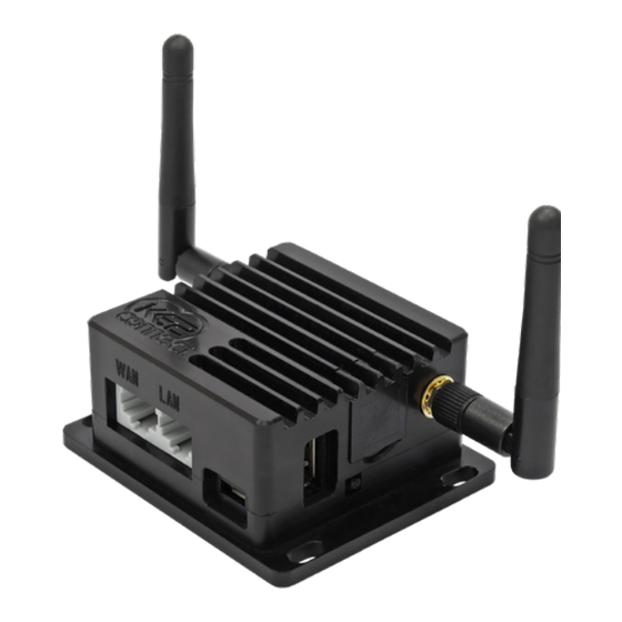
KE2-EM35
KE2 Edge Manager (KE2-EM35)
Overview, Installation, and Setup Instructions V1.1 PN 21634
Connecting up to 35 KE2 Therm controllers and
sensors in one view, and letting you access and
control each individual device.
KE2 Therm's Edge Manager - 35 is the perfect
addition to your Refrigeration Network.
When the KE2-EM35 is connected to the same network as KE2
Therm devices, it immediately and automatically scans and
finds all KE2 Therm controllers - Ethernet and Serial (Modbus)*,
or KE2 Wireless Sensors.
Display a Local Area Dashboard showing controllers
½
connected to the customer's network
Connect controllers to KE2 SmartAccess customer portal
½
without requiring controller upgrades
Send e-mail Alarms to multiple e-mail recipients
½
View Serial (Modbus) devices in a webpage, make changes to
½
setpoints and receive alerts via e-mail or text message
Local data logging with an option for Advanced data logging
½
to MQTT server, SQL server, or Amazon services
Wirelessly tether to the local network (Wirelessly connect a controller to existing Wi-Fi)
½
BACnet Integration (currently for KE2-Evap Efficiency & sensors only)
½
Statically assign IP addresses to both WAN and LAN ports
½
The KE2-EM35 allows customers to locally view all of their controllers/sensors in a single
view, without a recurring fee. Additionally, KE2-EM35 enables customers to access their
controllers over the internet, by functioning as a conduit to KE2 SmartAccess (available for
a nominal monthly charge.)
* Serial (Modbus) devices must be enabled, see Page 8.
5ft. Ethernet Cable
Power Plug
RS45 Connector
© Copyright 2021 KE2 Therm Solutions, Inc., Washington, Missouri 63090
Q.5.62 February 2021
Wireless Sensors
(Sold separately, in 10-packs or included
in KE2-EM35 Kit pn 21660)
KE2 Wireless Sensor
pn 21632 - Individual Sensor
pn 21687 - 10-pack of Sensors
KE2 Wireless Sensor w.
Remote Probe
pn 21633 - Individual Sensor
pn 21688 - 10-Pack of Sensors
Advertisement
Table of Contents

Related Manuals for KE2 Therm Solutions KE2-EM35

Summary of Contents for KE2 Therm Solutions KE2-EM35
-
Page 1: Table Of Contents
Wireless Sensors Kit pn 21634 - includes the KE2-EM35 & Accessories shown below Kit pn 21660 - includes the KE2-EM35 & Accessories shown below, plus (3) KE2 Wireless Sensors pn 21632, (Sold separately, in 10-packs or included & (2) KE2 Wireless Sensors with Remote Probe shown at right... -
Page 2: Options For Connecting To The Ke2-Em35 - Page 2 To
Daisy chain powered controllers to KE2-EM35 adapter. Assign unique addresses. Power to the KE2-EM35. Internet provided by WAN port of the KE2-EM35 is connected to the same network connecting WAN port to customer network or tethering to exist- or tethered to existing in-house Wi-Fi. This should give the KE2- ing in house Wi-Fi. - Page 3 KE2 Temp +Air Defrost KE2 Temp + Valve Control Evaporator Fan All Clear Superheat Suct Pressure Suct Temp 0.0 F 96.2 F 87.7 F KE2 Low Temp KE2 Adaptive Control PC/Laptop © Copyright 2021 KE2 Therm Solutions, Inc., Washington, Missouri 63090...
- Page 4 10.10.x.x controllers can only be managed by ENTER Press and hold for manual defrost BACK Press and hold for PC, phone, or tablet when wirelessly connected manual defrost to the KE2-EM35. © Copyright 2021 KE2 Therm Solutions, Inc., Washington, Missouri 63090...
-
Page 5: Option 5 - Controllers Connected & Addressed On Customer ¨ Network
Press and hold for manual defrost er, 10.10.x.x controllers can only be managed by BACK Press and hold for manual defrost PC, phone, or tablet when wirelessly connected to the KE2-EM35. © Copyright 2021 KE2 Therm Solutions, Inc., Washington, Missouri 63090... - Page 6 Q.5.62 February 2021 Page 6 KE2 EdgeManager (KE2-EM35) Overview, Installation, and Setup Instructions Installing the KE2-EM35: Option 2 & 4 & 5 Combined Connecting Serial (Modbus) & Customer Connected Controllers EM Connnection - Setup A Setup / Manage EM EACH DEVICE MUST HAVE A SEPARATE/...
-
Page 7: Access The Local Dashboard
Dashboard tab, or close the current tab Similar to the controllers themselves, the KE2-EM35 can also be viewed online, us- ing either port forwarding or through a Virtual Private Network (VPN). © Copyright 2021 KE2 Therm Solutions, Inc., Washington, Missouri 63090... -
Page 8: Serial (Modbus) Access
❹ To access Advanced View click on the Show Advanced View. Advanced View ❺ TClick on the ? in any of the setpoint areas show limits those setpoints. For example Room Temperature. © Copyright 2021 KE2 Therm Solutions, Inc., Washington, Missouri 63090... - Page 9 ❾ For security purposes, Logout when finished making all Serial (Modbus) changes. ❿ The Success image will display to verify that you have successfully logged out. © Copyright 2021 KE2 Therm Solutions, Inc., Washington, Missouri 63090...
-
Page 10: Remote Access Setup
FCC ID: 2AOPP-216345 IC:23545-21634 FCC ID:XU8TBW106-107V2 For example if the KE2-EM35’s Mac Address is E4:95:40:4B:5D:7F the Password is E4-95-40-4B-5D:7F KE2 Therm recommends changing this as well. © Copyright 2021 KE2 Therm Solutions, Inc., Washington, Missouri 63090... - Page 11 Sample screenshot when accessing via cell phone. ❼ Use the site name and credentials you setup, (Steps 3 and 4 on page 10) to access your site. © Copyright 2021 KE2 Therm Solutions, Inc., Washington, Missouri 63090...
- Page 12 KE2 SmartAccess server. By checking the Disconnected box under State, an e-mail will be sent if the controller does not check in with our server for a matter of 10 minutes. © Copyright 2021 KE2 Therm Solutions, Inc., Washington, Missouri 63090...
- Page 13 KE2-EM35. ⓭ Click the Licenses drop down to easily purchase KE2 Smart Access. For additional information on KE2 Smart Access see bulletin Q.1.34. KE2 Smart Access Customizing and Setup. © Copyright 2021 KE2 Therm Solutions, Inc., Washington, Missouri 63090...
-
Page 14: Manage E-Mail Alerts
❷ To enable alerting, click the box next to Alerts For questions pertaining to the Alerts, click on the ? near the top right on the screen. © Copyright 2021 KE2 Therm Solutions, Inc., Washington, Missouri 63090... - Page 15 ❹ Please note: Only selected control- lers will send alerts. Click the bell to the left of the device you would like to receive e-mails from when in alarm state. © Copyright 2021 KE2 Therm Solutions, Inc., Washington, Missouri 63090...
-
Page 16: Data Logging
Icon to the left of the devices you would like to log. ❹ Enabling fewer than 35 devices for logging does not increase the available space for logging. © Copyright 2021 KE2 Therm Solutions, Inc., Washington, Missouri 63090... -
Page 17: Advanced Logging
Logging to local servers or Amazon online account. Option A: MQTT Settings Option B: MSSQL Option C: Push Settings Record all available fields for controllers/ sensors to Advanced Logging Servers. © Copyright 2021 KE2 Therm Solutions, Inc., Washington, Missouri 63090... -
Page 18: Bacnet
Must be wired to the LAN to complete the Tether and give the Tether Only - KE2-EM35 a connection to the Internet. There will no longer be a Wi-Fi SSID to connect to. To manage the KE2-EM35 will require a hard wired connection to the LAN. -
Page 19: Option 3 - Tethering To Hidden Ssid
KE2EDGE-xxxxxx profile will no longer be seen. displayed in a field is strictly a place holder. ❶ Enter desired IP Address ❷ Enter Subnet Mask ❸ Check the box to statically assign IP address © Copyright 2021 KE2 Therm Solutions, Inc., Washington, Missouri 63090... - Page 20 Room temp setpoint. Click select all or pick indi- vidually, enter a value then click Save & Run Config. Coordinate Devices: Used primarily ½ for Escalation Notifications. © Copyright 2021 KE2 Therm Solutions, Inc., Washington, Missouri 63090...
- Page 21 KE2-EM35 to factory settings, i.e. ke2admin for all User and Passwords. This will also reset the wireless creden- tials, to those listed on the back label of the KE2-EM35. © Copyright 2021 KE2 Therm Solutions, Inc., Washington, Missouri 63090...
- Page 22 Upload Firmware: For EM35 with no ½ internet connection. Update file can be sent to a PC with internet. From there the file can be uploaded to update the firmware. © Copyright 2021 KE2 Therm Solutions, Inc., Washington, Missouri 63090...
-
Page 23: Field Update Process
❸ Click Update Firmware button. ❹ Click Start ❺ Click Reboot. During the update and reboot process the LEDs will blink in sequence. IMPORTANT: Do not power cycle the KE2-EM35 during this process. © Copyright 2021 KE2 Therm Solutions, Inc., Washington, Missouri 63090... -
Page 24: Allowing Vendor Assist
You will need to republish your devices after clicking the Stop button. This would be beneficial if moving to a new network or new IP addressing scheme. © Copyright 2021 KE2 Therm Solutions, Inc., Washington, Missouri 63090... -
Page 25: Appendix A Serial (Modbus) Configuration
STEP 1- Daisy chain connections on controllers (See Appendix B). STEP 2 - Finish wiring controllers to pluggable connector. The setting change can be verified by pressing the button. Do not plug into KE2-EM35 or power on KE2-EM35 To exit, press the button several times. STEP 4 -... -
Page 26: Appendix B Serial (Modbus) Wiring
KE2 Therm Solutions, Inc. © Copyright 2021 KE2 Therm Solutions, Inc., Washington, Missouri 63090 Q.5.62 February 2021 supersedes Q.5.62 February 2019 and all prior publications. 12 Chamber Drive . Washington, Missouri 63090 ph: 636.266.0140 . fx: 888.366.6769...
Need help?
Do you have a question about the KE2-EM35 and is the answer not in the manual?
Questions and answers