Table of Contents
Advertisement
Quick Links
Advertisement
Table of Contents

Summary of Contents for OmarLift SIEMENS SINAMICS V20
- Page 1 INVERTER SIEMENS V20 Siemens V20_EN_rev01-08032019.docx...
-
Page 2: Table Of Contents
Sommario ................................0-0 INTRODUCTION ............................ 1-1 SAFETY INSTRUCTIONS AND PRECAUTIONS .................. 2-1 SAFETY INSTRUCTIONS ......................2-1 PRECAUTIONS ..........................2-1 POWER MODULE ..........................3-1 POWER MODULE V20 ........................3-1 3.1.1 Description ..........................3-1 3.1.2 Warnings ..........................3-1 3.1.3 Terminal description ....................... 3-2 3.1.4 Dimension drawings ....................... - Page 3 10.1 DISPLAY PARAMETERS ......................10-9 10.2 INVERTER COMMISSIONING..................... 10-9 10.3 PARAMETER LIST ........................10-9 10.4 CONFIGURATION PARAMETERS ....................10-9 10.4.1 Upwards ..........................10-9 10.4.2 Power limitation........................10-10 10.4.3 Downward ........................... 10-11 10.5 RUPTURE VALVE TEST ......................10-11 ACTIVE FAULTS & ALERT ......................11-11 11.1 FAULT CODES ...........................
-
Page 4: Introduction
1 INTRODUCTION SIEMENS V20 is an inverter with a specialized software in hydraulic systems, which controls only the up- ward travel. These inverters SIEMENS can be applied to both pump units of the old generation, and pump units most re- cent and modern. -
Page 5: Safety Instructions And Precautions
2 SAFETY INSTRUCTIONS AND PRECAUTIONS Read all of this manual before powering the equipment, following step by step the procedures. SAFETY INSTRUCTIONS Carefully follow the procedures given below, to prevent the risk of serious accidents. 1- The leakage current from the inverter to earth is greater than 30mA, therefore a differential switch with Id of at least 300mA, type B or type A, must be provided. -
Page 6: Power Module
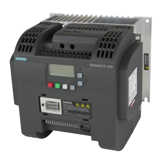
3 POWER MODULE POWER MODULE V20 3.1.1 Description SINAMICS V20 is a family of inverters developed to control the speed of asincronous motors. The inverters are available in many frame sizes. Rated Rated out- Order number Rated in- Component output put num- put current Filtered... -
Page 7: Terminal Description
3.1.3 Terminal description Terminal layout Siemens V20_EN_rev01-08032019.docx... -
Page 8: Dimension Drawings
3.1.4 Dimension drawings Frame size C Siemens V20_EN_rev01-08032019.docx... -
Page 9: Wiring
3.1.5 Wiring 3.1.5.1 Cables WARNING: Contact with live parts can result in death or serious physical injury Motor / DC / braking resistor / output Rated Mains and PE terminals earth terminals Frame output size Cable cross- Screw tightening torque Cable cross- Screw tightening torque power... -
Page 10: Technical Data
3.1.6 Technical data V20 with filter 6SL3210 5BB23-0 Input current Voltage 200 ÷ 240V 1AC Frequency 47 ÷ 63 Rated current Output current Rated current In 13,6 Peak current Imax 20,4 Overload MAX 150% In x 60s + 24,5% In x 240s Rated pulse frequency Power loss 0,114... -
Page 11: Emc-Compliant Installation (Emc)
4 EMC-COMPLIANT INSTALLATION (EMC) Together with a system configuration in conformity with EMC standards (see norms EN 61000-6-2, EN61000-6-4, EN60204-1), the line filters limit the conducted interference emitted by the Power Modules to limit values according to standard EN61800-3. For PM this is obtained by mains integrals filters. The PM with a suitable line filter shall correspond to the category C2 for domestic installations, provided that: 1. - Page 12 The most cost-effective method of implementing interference suppression measures within the control cabi- net is to ensure that interference sources and potentially susceptible equipment are installed separately from each other. The control cabinet has to be divided into EMC zones and the devices within the control cabinet have to be assigned to these zones following the rules below.
-
Page 13: Braking Resistors
5 BRAKING RESISTORS The inverter handle only the upward travel in consequence of that, there are not cur- rents generated and MUST NOT BE INSTALLED ANY BRAKING RESISTOR. The downward direction is regulated by hydraulic valve. To adjust downward parameters, refer to the manual of the installed valve. -
Page 14: Control Unit
6 CONTROL UNIT DESCRIPTION The logical Control unit and adjustment is integrated in the power unit of the machine SAFETY WARNING WARNING Danger fire in case of overheating in case of insufficient free ventilation spaces: Absolutely observe a 50 mm clearance up and down the Control Unit and the Control Unit Adapter ... - Page 15 output Current range: 0 to 20 mA (4 to 20 mA - software se- lectable) Accuracy (0 to 20 mA): ± 1 mA Output capability: 20 mA into 500 R Overall reference potential for RS485 communication and analog inputs / output RS485 P + RS485 N -...
-
Page 16: Power Wiring
7 POWER WIRING POWER CIRCUIT CONNECTION All electrical wirings have to be done, respecting the rules shown in the table below: L1; L1 Mains power supply input Connect the mains power supply input phases in any order. Connect the three output phases to the contactors, then to the U;... - Page 17 without the shield connected to earth, as in this case any interference will be greater than with an unshielded cable. Any free or unused wires in a multicore cable must be connected to earth at both ends. 7- Any cable, for control or external connections for the shaft and lift car, must never run near and par- allel to the power cable, even if shielded;...
-
Page 18: Siemens V20 Electrical Wiring
SIEMENS V20 ELECTRICAL WIRING Permissible I/O terminal cable cross-sections Cable type Permissible cable cross-section Solid or stranded cable 0.5 to 1.5 mm Ferrule with insulating sleeve 0.5 mm 230V 3AC TO CONTACTORS Use shielded screw for analog inputs. Only with optional power limitation function. Siemens V20_EN_rev01-08032019.docx... -
Page 19: Programming Through Pc
8 PROGRAMMING THROUGH PC For the SIEMENS V20 inverter, is not available an interface tool for parameters programming directly via PC; therefore it is necessary to proceed in case of parameters values modification by using the keypad and the screen supplied on the front of the inverter (BOP). 9 PROGRAMMING THROUGH KEYBOARD AND MENU EXPANSION PORT (Optional) The expansion port (optional) is designed for connecting the inverter to the external option module... - Page 20 Note: If configured to be an OFF1 stop, this button is inactive in AUTO mode. Double press (< 2 s) or OFF2 stop reaction: the inverter allows the motor to coast long press ( > 3 s) to a standstill without using any ramp-down times. Starts the inverter If the inverter is started in HAND / JOG mode, the inverter running icon ( ) displays.
-
Page 21: Inverter Menu
Inverter status icons At the top of the display, may appear the following icons: Inverter has at least one pending fault. Inverter has at least one pending alarm. Inverter is running (motor speed may be 0 rpm). Inverter may be energized unexpectedly (for example, in frost pro- (flashing): tection mode). -
Page 22: Viewing Inverter Status
9.2.2 Viewing inverter status The display menu provides a basic monitoring view of some key parameters such as frequency, voltage, current, and so on 9.2.3 Editing of parameters This section explains how to edit the parameters. Some parameters are indexed because contain more values inside them. Normal editing of parameters Note: Pressing ▲... -
Page 23: Screen Displays
Pressing M once moves the cursor to the rightmost digit of the current item. Pressing M twice in succession exits the digit-by-digit mode without changing the item being edited. Pressing OK on a digit when there are no further digits to the left saves the value. ... -
Page 24: Led Warnings
“Fxxx” Parameter value in hex format “Axxx” Alarm code “Cnxxx” Settable connection macro “-Cnxxx” Current selected connection macro “APxxx” Settable application macro “-APxxx” Current selected application macro 9.2.5 LED warnings The SINAMICS V20 has only one LED for status indications. The LED can display orange, green, or red. For example, if there is an active fault when the inverter is in the commissioning mode, the LED flashes green at 0.5 Hz. -
Page 25: Setting Motor Data
9.3.2 Setting motor data Functionality Parameter setup is already made by Omarlift. After a factory reset may be necessary to set the param- eter setup. (Please, contact Omarlift Service). Setting parameters In the menu setup (→ 9.2.2) the value of this parameter must be entered according to the rating plate of the motor. -
Page 26: Setting Connection-Macros
Failure to observe may cause the inverter to accept the parameter settings from both the currently and the previously selected macros, which may lead to undefined and unexplainable inverter operation. After a factory reset may be necessary to set the connection macro settings (Please, contact Omarlift Service). 9.3.4 Setting application macros WARNING: DON’T EDIT THE APPLICATION MACRO SETTINGS... -
Page 27: Parameters
Power limitation ATTENTION: Only in case of change of the inverter or of the electric motor, you must do motor recognition by P1900, before performing any calibration. Please contact Omarlift Service, for the procedure. PARAMETER LIST 10.3 Parameter Description... -
Page 28: Power Limitation
Sequence controls Upward: 1- Insertion of the UPWARD command then, when the contactors are closed, a signal has to arrive to the ENABLE input: this will enable the starting of the motor. If you enable the High speed, the motor runs at a speed "high". If you do not enable any speed level (eg. -
Page 29: Downward
In all other cases the operation will be according to standard parameter value. The pressure threshold is adjustable by acting directly on the pressure switch regulation) Don’t set the reduced high speed value, too low: always respect P1007 >30Hz 10.4.3 Downward Refer to the manual of the installed valve. -
Page 30: Fault Codes
If the fault has not been cleared and the button is pressed, the faults screen displays again. If there is no key press for 60 seconds. If a fault is active and there has been no key press for 60 seconds, the backlight (P0070) flashes. FAULT CODES 11.1 Fault... -
Page 31: Alert Codes
Motor power (P0307) exceeds invert- Motor power (P0307) must match invert- er power capability (r0206). er power (r0206) Note: F5 cannot be cleared until the inverter overload utilization (r0036) is lower than the inverter I t warning (P0294). ... - Page 32 junction temperature, or allowed r0037 = 1: Chip junction temperature Inverter overtempe- change in temperature on chip (includes heat sink) rature junction is exceeded, resulting in Check the following: Ambient temperature must lie within pulse frequency reduction and / or output frequency reduction (de- specified limits ...
-
Page 33: Checks And Maintenance
12 CHECKS AND MAINTENANCE To ensure long service life and optimum operation of the inverter, carry out the following checks at regular intervals. Operate on the inverter only after disconnecting the power and making sure the keypad is off. 1- Remove the dust collected on the cooling fins and on the control circuit board, if possible by blowing with compressed air or using a vacuum cleaner. - Page 34 OMARLIFT s.r.l. Via F.lli Kennedy, 22/D 24060 Bagnatica (BG) – ITALY Phone +39 035 689611 Fax +39 035 689671 Email: info@omarlift.eu Web: http://www.omarlift.eu...
Need help?
Do you have a question about the SIEMENS SINAMICS V20 and is the answer not in the manual?
Questions and answers