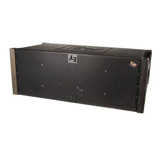
Electro-Voice XLC127 Rigging Manual
Hide thumbs Also See for XLC127:

Advertisement

Includes the following XLC Loudspeaker Models
and Rigging Accessories -
XLC127 (updated structural model only)
XLC127+ (updated structural model only)
XLC118 (updated structural model only)
XLC127DVX (new loudspeaker system)
XLC907DVX (new loudspeaker system)
A1 Grid (updated rigging accessory)
B1 Grid (new rigging accessory)
XLC-EB Extender Beam (new rigging accessory)
Electro-Voice XLC Touring Addendum
Addendum to
XLC Touring
Rigging Manual
October 2009

Advertisement

Table of Contents
loading

Summary of Contents for Electro-Voice XLC127

  • Page 1 Addendum to XLC Touring Rigging Manual Includes the following XLC Loudspeaker Models and Rigging Accessories - • XLC127 (updated structural model only) • XLC127+ (updated structural model only) • XLC118 (updated structural model only) • XLC127DVX (new loudspeaker system) •...
  • Page 2: Table Of Contents

    3.3 Simplified Structural-Rating Guidelines ............................ 18 3.4 Complex Structural-Rating Analysis ............................19 3.5 XLC127, XLC127+, XLC127DVX, XLC907DVX, XLC118, and XLC215 Structural-Strength Ratings ....20 XLC Front Rigging Hinge Bar Structural Ratings ......................20 XLC Rear Rigging Swing Arm Structural Ratings ......................20 XLC Overall Enclosure Structural Ratings ........................
  • Page 3: Introduction

    Electro-Voice that allows either biamp or triamp operation. The XLC127DVX utilizes the same 8° trapezoi- dal enclosure as the XLC127, XLC127+ and XLC907DVX, and has the same standard XLC 8° rigging frame secured to the left and right enclosure sides.
  • Page 4 XLC127: 116 lb (52.6 kg) XLC127+: 111 lb (50.3 kg) XLC127DVX: 114 lb (51.7 kg) XLC907DVX: 114 lb (51.7 kg) Figure 1: XLC127, XLC127+, XLC127DVX and XLC907DVX dimensions and weights Front View Side View Rear View System Weights - XLC118: 120 lb (54.4 kg) XLC215: 140 lb (63.5 kg)
  • Page 5: Xlc Rigging System

    All enclosure, rigging hardware dimensions and centers of gravity are shown in Figure 1 for the XLC127, XLC127+, XLC127DVX and XLC907DVX loudspeaker systems, and in Figure 2 for the XLC118 and XLC215 systems.
  • Page 6 (1 Spreader Bar) - 49.6 lb (22.50 kg) 30.0 lb (13.61 kg) A1 Spreader Bar - A1 Sidearm - 19.6 lb (8.89 kg) 5.2 lb (2.36 kg) Figure 3b: XLC A1 Grid rigging dimensions and weight Electro-Voice XLC Touring Addendum...
  • Page 7 (1 Ring Assembly) - 31.0 lb (14.1 kg) XLC-EB Frame Subassembly - 23.9 lb (10.8 kg) XLC-EB Ring Subassembly - XLC-EB Yoke Subassembly - 1.5 lb (0.7 kg) 2.8 lb (1.3 kg) Figure 3c: XLC-EB rigging dimensions and weight Electro-Voice XLC Touring Addendum...
  • Page 8: Rigging And Flying Techniques

    The center of gravity of all current subwoofer systems (XLC118 and XLC215) and all older full-range loudspeaker systems (XLC127 and XLC127+) is centered left to right. The older XLC A1 grids had one hole in the center of the spreader bar when using a center pick point on the grid.
  • Page 9 Step 3: Step 4: Assemble spreader bar(s) Insert quick-release pins through to sidearms. sidearms and spreader bar(s) using the hole locations from LAPS. See Figures 4b - 4g for fully assembled configurations. Figure 4a: Grid rigging assembly Electro-Voice XLC Touring Addendum...
  • Page 10 The center of gravity of the enclosures is only a concern when using a single pick point on the spreader bar(s). The A1 grid may be used for lifting XLC127, XLC127+, XLC118 or XLC215 loudspeaker systems, as shown in Figure 4g. However, the A1 grid is not compatible with the XLC127DVXand XLC907DVX loudspeaker systems when using a single pick point on the spreader bar(s) The A1 grids may be modified to become B1 grids.
  • Page 11 Figure 4b: XLC B1 Grid configurations for any XLC Array Single Bar/Single Pull = Use Hole “B” Dual Bar/Single Pull = Use Hole “B” Figure 4c: XLC B1 Grid configurations for XLC127, XLC127+, XLC118 or XLC215 Arrays Electro-Voice XLC Touring Addendum...
  • Page 12 Dual Bar/Single Pull = Use Hole “A” (Note that the bar is reversed) (Note that the bar is reversed) Figure 4e: XLC B1 Grid configurations for XLC127DVX or XLC907DVX with XLC118 or XLC215 in the same array Electro-Voice XLC Touring Addendum...
  • Page 13 Figure 4f: XLC A1 Grid configurations for any XLC Array Single Bar/Single Pull = Use Center Hole Dual Bar/Single Pull = Use Center Hole Figure 4g: XLC A1 Grid configurations for XLC127, XLC127+, XLC118 or XLC215 Arrays Electro-Voice XLC Touring Addendum...
  • Page 14: Rigging The Xlc Grids And The Xlc-Eb

    ALWAYS MAKE SURE THAT EACH QUICK-RELEASE PIN SECURING EACH GRID SPREAD- ER BAR IS FULLY LOCKED IN EACH YOKE. Pickup Ring Centering Ring Extender Beam Quick-Release Pin Figure 5a: Yoke Note: Extender Beam XLC-EB rigging assembly shown cutaway for better conceptualization and clarity. Quick-Release Pin Grid Electro-Voice XLC Touring Addendum...
  • Page 15 XLC-EB array configurations Step 1: Install Pickup Rings Step 2: Rotate Yokes, then drop Pickup Rings in Hole #18 and #22 and (View shown cutaway for clarity) Install Yokes as shown. Figure 5c: XLC-EB shipping/transport configuration Electro-Voice XLC Touring Addendum...
  • Page 16: Rigging Strength Ratings, Safety Factors, And Special Considerations

    The working-load limits defined by the manufacturer of any rigging component should never be exceeded. Electro-Voice bases the working-load limits of its XLC products on a minimum of an 8:1 safety factor. Other manufacturers of rigging components may base their working-load limits on safety factors other than 8:1.
  • Page 17: Structural Rating Overview

    Determining the forces throughout an array requires complex mathematical calculations. Electro-Voice engineers have, however, defined a set of simplified structural-rating guidelines that eliminate the need for the complex calculations for most array configura- tions.
  • Page 18: Simplified Structural-Rating Guidelines

    3. Rigging Strength Ratings/Safety Factors/Special Considerations 3.3 Simplified Structural-Rating Guidelines Electro-Voice engineers have defined a set of simplified structural-rating guidelines that will enable a rigger to immediately evaluate the safety of an XLC system on site without having to make complex force- distribution calculations.
  • Page 19: Complex Structural-Rating Analysis

    The reader should consult an experienced structural engineer to perform the complex structural analysis. WHEN SUSPENDING ANY XLC LOUDSPEAKER SYSTEM OVERHEAD, THE WORKING- LOAD LIMITS MUST NEVER BE EXCEEDED FOR EACH INDIVIDUAL RIGGING POINT, AND THE OVERALL ENCLOSURE. Electro-Voice XLC Touring Addendum...
  • Page 20: Xlc127, Xlc127+, Xlc127Dvx, Xlc907Dvx, Xlc118 And Xlc215 Structural-Strength Ratings

    Thus, the rear swing arm will always be axially loaded. For the XLC127, XLC127+, XLC127DVX and XLC907DVX, a tensile force can only be applied over an angle range of negative 0°-8°, while the XLC-118 and XLC215 can only have a tensile over a range of negative 0°-12°.
  • Page 21: Xlc Overall Enclosure Structural Ratings

    This simplified working-load weight rating of the overall enclosures is defined as being independent of the angles of pull on the individual rigging points. The Electro-Voice engineers have chosen to define the working-load limits of the individual rigging points as a function of pull angle so that they take into account any variations in enclosure strength that might occur as a func- tion of pull angle.
  • Page 22: A1, B1 And Xlc-Eb Complex Structural-Strength Ratings

    The Electro-Voice engineers have designed the XLC A1 and B1 grids to be stronger than the XLC loud- speaker systems over the entire mechanical operating range of the loudspeaker systems. This makes the...
  • Page 23: Xlc-Eb Complex Structural-Strength Ratings

    3. Rigging Strength Ratings/Safety Factors/Special Considerations XLC-EB Complex Structural-Strength Ratings The XLC-EB is used as an extender beam with a single column of XLC127, XLC127+, XLC127DVX, XL- C907DVX, XLC118 and XLC215 loudspeaker systems to enable greater vertical angle tilt of the column than that which could be achieved with a grid alone.
  • Page 24: Rigging Inspection And Precautions

    Never exceed the limitations or maximum recommended load for the XLC loudspeaker systems. Electro-Voice XLC Front Rigging Hinge Bar Assemblies: Prior to each use, inspect the front rigging hinge bars and the front rigging tubes for any cracks, burrs, deformations, corrosion or missing or dam- aged components that could reduce hinge bar assembly strength.
  • Page 25 Replace any damaged mechanical components. Never exceed the limitations or maximum recommended load for the mechanical components. Electro-Voice XLC Touring Addendum...
  • Page 26: Notes

    5. Notes Electro-Voice XLC Touring Addendum...
  • Page 27 5. Notes Electro-Voice XLC Touring Addendum...
  • Page 28 Other Internatonal locations. For customer orders, Contact Customer Service at: + 1 952 884-4051 Fax: + 1 952 887-9212 www.electrovoice.com For warranty repair or service information, contact the Service Repair department at: Electro-Voice XLC Touring Addendum 800/685-2606 © Bosch Communications Systems 10/2009...

This manual is also suitable for:

Xlc127+Xlc118Xlc127dvxXlc907dvx

Table of Contents