Table of Contents
Advertisement
Quick Links
DP5 User Manual and Operating Instructions
Other DP5 related documents:
•
DP5 Quick Start Guide
•
DP5 Programmer's Guide
•
DP5 Product Change Document
•
PC5 User Manual
•
Grounding and Shielding the DP4 Product Family
Amptek Inc.
Amptek, Inc.
14 DeAngelo Dr.
Bedford, MA 01730
PH: +1 781-275-2242 FAX: +1 781-275-3470
sales@amptek.com www.amptek.com
DP5 User Manual Rev A1
Page 1 of 31
Advertisement
Table of Contents

Related Manuals for Amptek DP5

Summary of Contents for Amptek DP5
- Page 1 DP5 User Manual Rev A1 DP5 User Manual and Operating Instructions Amptek, Inc. 14 DeAngelo Dr. Bedford, MA 01730 PH: +1 781-275-2242 FAX: +1 781-275-3470 sales@amptek.com www.amptek.com Other DP5 related documents: • DP5 Quick Start Guide • DP5 Programmer’s Guide •...
-
Page 2: Table Of Contents
Software ............................26 Interface Software ........................26 Embedded Software ........................26 Application notes ..........................27 Troubleshooting and Advice .......................27 Use of the DP5 with Amptek Detectors ..................27 7.2.1 Users with an XR100......................27 7.2.2 Users with a PA-210 or PA-230 Preamplifier ..............28 How to configure the analog prefilter for custom applications ............29 7.3.1... -
Page 3: Introduction
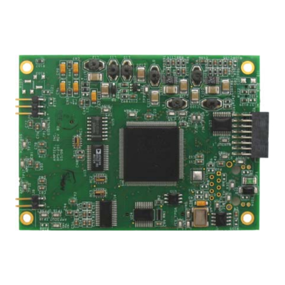
DP5 has been used with scintillator/PMT systems, proportional counters, and a wide variety of other detectors. The DP5 is a printed circuit board assembly, suited primarily to OEM applications as part of a complete system. -
Page 4: Understanding The Dp5
Figure 2-1. Block diagram of a Digital Pulse Processor (DPP) in a complete system. Analog Prefilter: The input to the DP5 is the output of a charge sensitive preamplifier. The analog prefilter circuit prepares this signal for accurate digitization. The main functions of this circuit are (1) applying appropriate gain and offset to utilize the dynamic range of the ADC, and (2) carrying out some filtering and pulse shaping functions to optimize the digitization. -
Page 5: Analog Prefilter
The DPP includes USB, RS232, and Ethernet interfaces. The DP5 also includes a power interface. It takes a loosely regulated 5VDC input and generates the various levels required by the circuitry (+/- 5.5V, 3.3V, 2.5V). - Page 6 Figure 2-3. Block diagram of the analog prefilter in the DP5. By default, the analog prefilter of the DP5 is configured for use with Amptek’s XR100CR family of detectors: solid state X-ray detectors with a reset preamplifier. The DP5 can certainly be used with other detectors, but this will most often require changing the analog prefilter settings or circuit changes.
-
Page 7: Pulse Shaping
The analog prefilter of the DP5 has a standard configuration which is suitable for Amptek’s XR100 family of detectors, using reset preamplifiers with fairly high gain. By appropriate configuring the prefilter, the DPP can be used with many other detectors and preamps. - Page 8 DP5 User Manual Rev A1 The user can adjust the rise/fall time (the rise and fall must be equal) and the duration of the flat top A semi-Gaussian amplifier with shaping time τ has a peaking time of 2.2τ and is over many steps.
-
Page 9: Pulse Selection
DP5 User Manual Rev A1 The peak of the “baseline” of a digital processor has some significant differences from traditional analog shaping amplifiers. Because the DPP’s transfer function has a finite impulse response, after a pulse has passed through the processing pipeline it has no impact on the output. This is fundamentally different from an analog differentiator and results in vastly enhanced baseline stability at high count rates. - Page 10 Risetime discrimination rejects from the spectrum events with a long detector current, which leads to a slowly rising edge in the fast and slow shaped pulses. The DP5 implements RTD by comparing the peak height in the fast channel (which samples the charge integrated in the first 100 nsec) to the peak height in the slow channel (which samples the charge which is eventually integrated).
-
Page 11: Mca, Mcs, Counters, And Scas
DP5 uses 3 bytes per channel, which allows up to 16.7M counts per channel. The MCA hardware in the DP5 can be started and stopped by commands over the serial bus. It can also be preset to stop after a programmed acquisition time (with a minimum of 100 milliseconds) or after a programmed number of counts has been measured within the SCA8 region of interest (see below). -
Page 12: Electrical & Software Interfaces
An additional counter records those events rejected by PUR and RTD. This is generally not of direct use but can be a “quality assurance” value by which one can verify system operation. The DP5 also includes an external counter, an external TTL input to a counter which is started and stopped at the same time as the other counters. - Page 13 Amptek’s ADMCA software provides the quickest way to control and readout the DP5. It provides access to all of the configuration parameters in the DP5, lets one start and stop data acquisition, reads and displays the data, performs very simple analyses, and saves the data in an ASCII format. The files saved by ADMCA can be read by many spectral processing software packages.
-
Page 14: Specifications
Detector and Preamplifier Compatibility The DP5 can be configured for use with most detectors and preamplifiers. In its usual factory configuration, it is ready for use with semiconductor detectors using reset type preamplifiers. It accepts inputs of either polarity. - Page 15 DP5 User Manual Rev A1 Presets Time, total counts, counts in an ROI, counts in a channel MCS Timebase 10 millisec/channel to 300 sec/channel External MCA Controls Gate input: Pulses accepted only when gated on by external logic. Input can be active high or active low.
- Page 16 RoHS Compliant Customization Amptek, Inc. provides many tailored configurations on an OEM basis and has designed the DP5 to be easily tailored and customized. This can include interfacing to external hardware (e.g. synchronizing with an external source or controlling external hardware), adding onboard processing, adding special purpose counters, etc.
-
Page 17: Electrical Interfaces
DP5 User Manual Rev A1 ELECTRICAL INTERFACES LECTRICAL SPECIFICATIONS 4.1.1 Absolute Maximum Ratings Operating Temperature -40°C to +85°C Power Supply Voltage +6.0 VDC Analog Input +6.0 to – 6.0 V NOTICE: Stresses above those listed under “absolute maximum ratings” may cause permanent damage to the device. -
Page 18: Auxiliary Input And Outputs
DP5 User Manual Rev A1 I/O 0 – I/O 3 Output High Voltage Output Low Voltage μA = GND = 1V =3.3V) with 50 Ω series resistance. □ The AUX OUT lines are the output of a 74LVC2G14 (V □... -
Page 19: Timing Of Auxiliary Inputs And Outputs
DP5 User Manual Rev A1 Single Channel Analyzers (SCAs) • Each of the eight SCAs has an independently assignable LLD and a ULD. If the shaped pulse peaks within the range of an SCA, between its LLD and ULD, then a logic signal is output. - Page 20 DP5 User Manual Rev A1 SCA output. Occurs just after the shaped pulse has begin to fall. One-Shot. Shows when the DPP is looking for possible pile-up. Triggered by the fast channel. Trigger. Shows when the DPP is looking for the peak of a pulse.
-
Page 21: Analog Input
• PS ENABLE: Open-drain output used by the DP5 to enable the PC5 power supplies. It is pulled low to turn OFF the PC5 supplies, and floated to turn ON the PC5 supplies. (The PC5 has a 10k pull-up to 3.3V on this signal.) -
Page 22: Power Supply Architecture
□ To power the DP5 from the USB bus, replace R118 by a zero ohm jumper. Note that this ties the USB bus to the J9 power input and the J5 interconnects. Only power the DP5 from one source at a time. If one attempts to power simultaneously from the USB bus and from an external supply, the two regulators will be “fighting”... -
Page 23: Mechanical Interface
DP5 User Manual Rev A1 MECHANICAL INTERFACE IMENSIONS Figure 5-1. DP5 bottom side, showing key interconnects. Figure 5-2. DP5 back/side view. ONNECTORS Power (J9) Power Jack on DP5: Hirose MQ172-3PA(55). Mating Plug:MQ172-3SA-CV Pin # Name VIN (+5 V DC) Do Not Connect Amptek Inc. - Page 24 Sleeve Main Interconnect (J5) The primary purpose of J5 is to connect the DP5 to the PC5, Amptek’s power supply board for Amptek preamplifiers and detectors. It provides input power in either direction, from DP5 to PC5 or vice-versa and permits the DP5 to control PC5 supplies.
- Page 25 Signal Input from PC5 (J3) This is a 2 x 2 connector with 2 mm spacing used to rout the input signal from the PC5 to the DP5. When the DP5 is used together with the PC5 and the PA-210/PA-230 preamplifier, the signal comes in on the PC5 through the same connector that supplies the preamp and detector power.
-
Page 26: Software
The DP5 comes with an Application Programming Interface (API) in the form of a DLL library. The user can use this library to easily write custom code to control the DP5 for custom applications or to interface it to a larger system. Examples are provided in VB, VC++, etc. on how to use the API. -
Page 27: Application Notes
(RS-232 is also available). Apply power to the system using the AC adapter. In the configuration shown below, both the DP5 and the PC5 are powered from the AC adapter. The DP5 passes the power to the PC5 which then generates the necessary voltages for the XR100. -
Page 28: Users With A Pa-210 Or Pa-230 Preamplifier
In this configuration both the signal from the preamplifier and the supply voltages to power the preamp and detector are passes through the flex cable that connects the PA-210/PA- 230 to the PC5 power board. The PC5 then passes the signal to the DP5 using the J3 connector (see section 5.2). -
Page 29: How To Configure The Analog Prefilter For Custom Applications
G = 4.704 G = 2.220 G = 1.000 Figure 7-4. Schematic of the analog prefilter circuit in the DP5. The analog prefilter circuit (Figure 7-4 includes four main Offset elements: (1) input buffer, (2) a high pass filter with a 3.2 μsec time The “offset”... -
Page 30: Preamplifier Tail Cancellation
DP5 User Manual Rev A1 7.3.2 Preamplifier Tail Cancellation The most common change required is to add a pole zero resistor to cancel the tail of a preamplifier with continuous feedback. The following procedure is suggested: Estimate the value of R102. If τ is the preamplifier time constant, the time in which the preamp tail decays to 1/e of its peak value after a step, then R102 = τ/6.8 nF. -
Page 31: Other Custom Configurations
Additionally, a 0Ω resistor should be installed in R139 and R77 removed. The input to the charge amp is pin 2 of J4 (the DP5 input is usually pin 1). In some cases, a large value resistor is installed in R77 (100k) for current limiting.
Need help?
Do you have a question about the DP5 and is the answer not in the manual?
Questions and answers