Asus ROG STRIX B660-F Gaming WiFi Manual
Hide thumbs
Also See for ROG STRIX B660-F Gaming WiFi:
- Quick start manual (2 pages) ,
- Quick start manual (2 pages)
Table of Contents
Advertisement
Advertisement
Table of Contents

Related Manuals for Asus ROG STRIX B660-F Gaming WiFi


Summary of Contents for Asus ROG STRIX B660-F Gaming WiFi
- Page 1 ROG STRIX B660-F GAMING WIFI...
- Page 2 Product warranty or service will not be extended if: (1) the product is repaired, modified or altered, unless such repair, modification of alteration is authorized in writing by ASUS; or (2) the serial number of the product is defaced or missing.
-
Page 3: Table Of Contents
Contents Safety information ...................... iv About this guide ......................v ROG STRIX B660-F GAMING WIFI specifications summary ........vi Connectors with shared bandwidth ................. xi Package contents ...................... xii Installation tools and components ................. xiii Chapter 1: Product Introduction Before you proceed ................... 1-1 Motherboard layout.................. -
Page 4: Safety Information
Safety information Electrical safety • To prevent electrical shock hazard, disconnect the power cable from the electrical outlet before relocating the system. • When adding or removing devices to or from the system, ensure that the power cables for the devices are unplugged before the signal cables are connected. If possible, disconnect all power cables from the existing system before you add a device. -
Page 5: About This Guide
Refer to the following sources for additional information and for product and software updates. ASUS website The ASUS website (www.asus.com) provides updated information on ASUS hardware and software products. Optional documentation Your product package may include optional documentation, such as warranty flyers, that may have been added by your dealer. -
Page 6: Rog Strix B660-F Gaming Wifi Specifications Summary
Extreme Memory Profile (XMP) ® Memory OptiMem II * Actual memory data rate depends on the CPU types and DRAM modules, for more information refer to www.asus.com for the Memory QVL (Qualified Vendors Lists). 1 x DisplayPort** 1 x HDMI port*** ®... - Page 7 ROG STRIX B660-F GAMING WIFI specifications summary 1 x Intel 2.5Gb Ethernet ® Ethernet ASUS LANGuard Wi-Fi 6 2x2 Wi-Fi 6 (802.11 a/b/g/n/ac/ax) Wireless & Bluetooth Supports 2.4/5GHz frequency band Bluetooth v5.2 Rear USB (Total 9 ports) 1 x USB 3.2 Gen 2x2 port (1 x USB Type-C ®...
- Page 8 ROG STRIX B660-F GAMING WIFI specifications summary Fan and Cooling related 1 x 4-pin CPU Fan header 1 x 4-pin CPU OPT Fan header 1 x 4-pin AIO Pump header 4 x 4-pin Chassis Fan headers Power related 1 x 24-pin Main Power connector...
- Page 9 ROG STRIX B660-F GAMING WIFI specifications summary AURA Sync Special Features - AURA RGB header - Addressable Gen 2 RGB headers ROG Exclusive Software - GameFirst VI - ROG CPU-Z - Sonic Studio III + Sonic Studio Virtual Mixer + Sonic Suite Companion...
- Page 10 • Specifications are subject to change without notice. Please refer to the ASUS website for the latest specifications. • MyASUS offers a variety of support features such as helping to troubleshoot issues, optimizing product performance, integrating ASUS software, and recovery drive...
-
Page 11: Connectors With Shared Bandwidth
Connectors with shared bandwidth ADD GEN2_2 CPU_FAN CPU_OPT ATX_12V_2 ATX_12V_1 HDMI DIGI+ CLRTC USB_56 BIOS_FLBK FLBK_LED U32G1_E3456 U32G2X2_C1 LAN_U32G2_3 LGA1700 M.2(WIFI) TYPE-C 22110 PCIE SATA M.2_1(SOCKET3) 4.0 X4 PCIEX16(G5) Ethernet Intel ® BATTERY B660 PCIEX1(G3)_1 SPI_TPM 256Mb BIOS PCIEX16(G3) 2280 2260 2242 2242... -
Page 12: Package Contents
Package contents Check your motherboard package for the following items. Motherboard 1 x ROG STRIX B660-F GAMING WIFI motherboard Cables 4 x SATA 6Gb/s cables 1 x ASUS Wi-Fi moving antenna 1 x Cable ties pack 1 x M.2 Rubber package 1 x M.2 Q-Latch package... -
Page 13: Installation Tools And Components
Installation tools and components Phillips (cross) screwdriver PC chassis Power supply unit Intel LGA 1700 CPU Intel LGA 1700 compatible CPU Fan ® ® DDR5 DIMM SATA hard disk drive SATA optical disc drive (optional) Graphics card (optional) M.2 SSD module (optional) 1 Bag of screws The tools and components in the table above are not included in the motherboard package. -
Page 15: Chapter 1: Product Introduction
Before you install or remove any component, ensure that the ATX power supply is switched off or the power cord is detached from the power supply. Failure to do so may cause severe damage to the motherboard, peripherals, or components. ROG STRIX B660-F GAMING WIFI... -
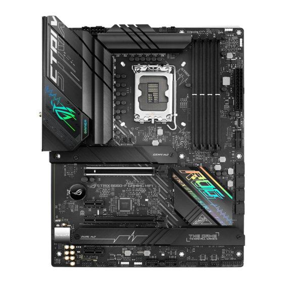
Page 16: Motherboard Layout
Motherboard layout 24.4cm(9.6in) ADD GEN2_2 CPU_FAN CPU_OPT ATX_12V_2 ATX_12V_1 HDMI DIGI+ CLRTC USB_56 BIOS_FLBK FLBK_LED U32G1_E3456 U32G2X2_C1 LAN_U32G2_3 LGA1700 M.2(WIFI) TYPE-C 22110 PCIE SATA M.2_1(SOCKET3) 4.0 X4 PCIEX16(G5) Ethernet Intel ® BATTERY B660 PCIEX1(G3)_1 SPI_TPM 256Mb BIOS PCIEX16(G3) 2280 2260 2242 2242 2260... - Page 17 13. Front Panel Audio header 1-16 14. S/PDIF Out header 1-16 15. SPI TPM header 1-17 16. System Panel header 1-17 17. Thermal Sensor header 1-18 18. Thunderbolt header 1-19 19. BIOS FlashBack™ LED 1-20 20. Q-LEDs 1-20 ROG STRIX B660-F GAMING WIFI...
- Page 18 Contact your retailer immediately if the PnP cap is missing, or if you see any damage to the PnP cap/socket contacts/motherboard components. ASUS will shoulder the cost of repair only if the damage is shipment/ transit-related.
- Page 19 A DDR5 memory module is notched differently from a DDR, DDR2, DDR3, or DDR4 module. DO NOT install a DDR, DDR2, DDR3, or DDR4 memory module to the DDR5 slot. Recommended memory configurations DIMM_A1 DIMM_A2 DIMM_A2 DIMM_A2 DIMM_B1 DIMM_B2 DIMM_B2 ROG STRIX B660-F GAMING WIFI...
- Page 20 (D/C) from the same vendor. Check with the vendor to get the correct memory modules. • Visit the ASUS website for the latest QVL. Chapter 1: Product Introduction...
- Page 21 Unplug the power cord before adding or removing expansion cards. Failure to do so may cause you physical injury and damage motherboard components. PCIEX16(G5) PCIEX1(G3)_1 PCIEX16(G3) PCIEX1(G3)_2 The PCIEX16(G3) shares bandwidth with the PCIEX1(G3)_1 and PCIEX1(G3)_2. When either PCIEX1(G3) slot enables, PCIEX16(G3) will run x2 mode. ROG STRIX B660-F GAMING WIFI...
- Page 22 Fan and Pump headers The Fan and Pump headers allow you to connect fans or pumps to cool the system. CPU_FAN CPU_OPT FAN PWM CHA_FAN1 FAN IN AIO_PUMP FAN PWR CHA_FAN4 CHA_FAN2 CHA_FAN3 • DO NOT forget to connect the fan cables to the fan headers. Insufficient air flow inside the system may damage the motherboard components.
- Page 23 • If you want to use two or more high-end PCI Express x16 cards, use a PSU with 1000W power or above to ensure the system stability. ROG STRIX B660-F GAMING WIFI...
- Page 24 M.2 slots The M.2 slots allow you to install M.2 devices such as M.2 SSD modules. M.2_1(SOCKET3) M.2_3(SOCKET3) M.2_2(SOCKET3) Intel Gen Processors: • ® M.2_1 slot (Key M), type 2242/2260/2280/22110 (supports PCIe 4.0 x4 mode) Intel B660 Chipset: • ® - M.2_2 slot (Key M), type 2242/2260/2280/22110 (supports PCIe 4.0 x4 mode) - M.2_3 slot (Key M), type 2242/2260/2280 (supports PCIe 3.0 x4 mode) •...
- Page 25 Intel Rapid Storage Technology through the onboard Intel B660 chipset. ® ® Before creating a RAID set, refer to the RAID Configuration Guide. You can download the RAID Configuration Guide from the ASUS website. ROG STRIX B660-F GAMING WIFI 1-11...
- Page 26 USB 3.2 Gen 2 Front Panel connector The USB 3.2 Gen 2 connector allows you to connect a USB 3.2 Gen 2 module for additional USB 3.2 Gen 2 ports. The USB 3.2 Gen 2 connector provides data transfer speeds of up to 10 Gb/s. U32G1_E12 PIN 1 USB3+5V...
- Page 27 The USB 2.0 headers provide data transfer speeds of up to 480 Mb/s. USB_E12 USB_E34 PIN 1 DO NOT connect a 1394 cable to the USB connectors. Doing so will damage the motherboard! The USB 2.0 module is purchased separately. ROG STRIX B660-F GAMING WIFI 1-13...
- Page 28 Addressable Gen2 header The Addressable Gen2 headers allow you to connect individually addressable RGB WS2812B LED strips or WS2812B based LED strips. ADD_GEN 2_2 ADD_GEN 2_1 ADD_GEN 2_3 The Addressable Gen2 header supports WS2812B addressable RGB LED strips (5V/ Data/Ground), with a maximum power rating of 3A (5V), and the addressable headers on this board can handle a combined maximum of 500 LEDs.
- Page 29 RGB LED strip is connected in the correct orientation, and the 12V connector is aligned with the 12V header on the motherboard. • The LED strip will only light up when the system is powered on. • The LED strip is purchased separately. ROG STRIX B660-F GAMING WIFI 1-15...
- Page 30 Front Panel Audio header The front panel audio header is for a chassis-mounted front panel audio I/O module that supports HD Audio. Connect one end of the front panel audio I/O module cable to this header. AAFP PIN 1 HD-audio-compliant pin definition We recommend that you connect a high-definition front panel audio module to this connector to avail of the motherboard’s high-definition audio capability.
- Page 31 The 2-pin and/or 3-1 pin headers allow you to connect the System Power LED. The System Power LED lights up when the system is connected to a power source, or when you turn on the system power, and blinks when the system is in sleep mode. ROG STRIX B660-F GAMING WIFI 1-17...
- Page 32 • Storage Device Activity LED header (HDD_LED) The 2-pin header allows you to connect the Storage Device Activity LED. The Storage Device Activity LED lights up or blinks when data is read from or written to the storage device or storage device add-on card. •...
- Page 33 Thunderbolt™-enabled devices to form a daisy chain-configuration. TB_HEADER PIN 1 • The add-on Thunderbolt™ I/O card and Thunderbolt™ cables are purchased separately. • Please visit the official website of your purchased Thunderbolt™ card for more details on compatibility. ROG STRIX B660-F GAMING WIFI 1-19...
- Page 34 BIOS FlashBack™ LED The FlashBack™ LED lights up or blinks to indicate the status of the BIOS FlashBack™. FLBK_LED Q-LEDs The Q-LEDs check key components (CPU, DRAM, VGA, and booting devices) during the motherboard booting process. If an error is found, the critical component’s LED stays lit up until the problem is solved.
-
Page 35: Chapter 2: Basic Installation
CPU designed for LGA1155, LGA1156, LGA1151, and LGA1200 sockets on the LGA1700 socket. • ASUS will not cover damages resulting from incorrect CPU installation/removal, incorrect CPU orientation/placement, or other damages resulting from negligence by the user. Take caution when lifting the load... - Page 36 Ensure to remove the CPU Socket lever protector on the lever latch before locking the lever latch under the retention tab. Failure to do so may cause damages to your system when installing the cooling system. Chapter 2: Basic Installation...
-
Page 37: Cooling System Installation
Ensure to remove the CPU Socket lever protector on the lever latch before installing the cooling system, failure to do so may cause damages to your system. To install a CPU heatsink and fan assembly ROG STRIX B660-F GAMING WIFI... - Page 38 Intel 600 series ® motherboard. • Additional holes for LGA1200 compatible cooling systems are also available on ASUS’ Intel 600 series motherboards, ® however, we still strongly advise consulting with your cooling system vendor or manufacturer on the compatibility and...
- Page 39 • If you wish to install an AIO cooler, we recommend installing the AIO cooler after installing the motherboard into the chassis. AIO_PUMP CPU_FAN CPU_OPT ROG STRIX B660-F GAMING WIFI...
-
Page 40: Dimm Installation
2.1.3 DIMM installation To remove a DIMM Chapter 2: Basic Installation... -
Page 41: Installation
Use a Phillips screwdriver when removing or installing the screws or screw stands mentioned in this section. • The M.2 is purchased separately. Loosen the screws from the M.2 heatsinks. Lift and remove the heatsinks. ROG STRIX B660-F GAMING WIFI... - Page 42 Install your M.2 to your M.2 slot. The steps may differ between installing M.2 of different lengths, please refer to the different types and their installation steps below: To install an M.2 to M.2_1 slot For 22110 length Remove the pre-installed M.2 Q-latch at the 2280 length screw hole by rotating the handle counterclockwise then pushing it towards the M.2 slot and removing it from the latch hole.
- Page 43 Rotate and adjust the M.2 Q-latch at the 2280 position so that the handle points away from the M.2 slot. Remove the plastic film from the thermal pad. Install your M.2 to the M.2 slot. Rotate the M.2 Q-Latch clockwise to secure the M.2 in place. ROG STRIX B660-F GAMING WIFI...
- Page 44 For 2242 and 2260 length Remove the pre-installed M.2 Q-latch at the 2280 length screw hole by rotating the handle counterclockwise then pushing it towards the M.2 slot and removing it from the latch hole. Remove the plastic film from the thermal pad. Remove the plastic film and thermal pad of the M.2 length screw hole you wish to install your M.2 to, then install the M.2 Q-latch.
- Page 45 Rotate and adjust the M.2 Q-latch so that the handle points away from the M.2 slot. Install your M.2 to the M.2 slot. Rotate the M.2 Q-Latch clockwise to secure the M.2 in place. OPTIONAL ROG STRIX B660-F GAMING WIFI 2-11...
- Page 46 For 2242, 2260 length (optional) Remove the M.2 rubber pad. Follow this step only if you wish to install an M.2 to type 2242. (optional) If required, remove the pre-installed removable M.2 Q-Latch screw at the 2280 length screw hole. Install the M.2 Q-Latch to the M.2 length screw hole you wish to install your M.2 to.
- Page 47 Remove the plastic film from the thermal pads on the bottom of the heatsink. Replace the heatsink. Secure the heatsink using the screws removed previously. ROG STRIX B660-F GAMING WIFI 2-13...
-
Page 48: Motherboard Installation
2.1.5 Motherboard installation Place the motherboard into the chassis, ensuring that its rear I/O ports are aligned to the chassis’ rear I/O panel. Place nine (9) screws into the holes indicated by circles to secure the motherboard to the chassis. DO NOT over tighten the screws! Doing so can damage the motherboard. -
Page 49: Atx Power Connection
2.1.6 ATX power connection Ensure to connect the 8-pin power plug. ROG STRIX B660-F GAMING WIFI 2-15... -
Page 50: Sata Device Connection
2.1.7 SATA device connection Chapter 2: Basic Installation 2-16... -
Page 51: Front I/O Connector
Push the connector until it clicks into place. To install USB 3.2 Gen 1 header To install USB 2.0 header USB 2.0 USB 3.2 Gen 1 To install front panel audio connector AAFP ROG STRIX B660-F GAMING WIFI 2-17... -
Page 52: Expansion Card Installation
2.1.9 Expansion card installation To install PCIe x16 cards To install PCIe x1 cards Chapter 2: Basic Installation 2-18... - Page 53 The TypeC_1 port can support up to 20V devices, and the TypeC_2 port can support up to 9V devices when the 6-pin PCIe power connector is connected. • Please visit the official website of your purchased Thunderbolt card for more details on compatibility. ROG STRIX B660-F GAMING WIFI 2-19...
-
Page 54: Wi-Fi Antenna Installation
2.1.10 Wi-Fi antenna installation Installing the ASUS Wi-Fi moving antenna Connect the bundled ASUS Wi-Fi moving antenna connectors to the Wi-Fi ports at the back of the chassis. • Ensure that the ASUS Wi-Fi moving antenna is securely installed to the Wi-Fi ports. -
Page 55: Bios Update Utility
• Updating BIOS may have risks. If the BIOS program is damaged during the process and results to the system’s failure to boot up, please contact your local ASUS Service Center. ROG STRIX B660-F GAMING WIFI... - Page 56 For more information on using the BIOS FlashBack™ feature, please refer to https://www. asus.com/support/, or by scanning the QR code below. Chapter 2: Basic Installation 2-22...
-
Page 57: Motherboard Rear And Audio Connections
We strongly recommend that you connect your devices to ports with matching data transfer rate. For example connecting your USB 3.2 Gen 1 devices to USB 3.2 Gen 1 ports for faster and better performance for your devices. ROG STRIX B660-F GAMING WIFI 2-23... - Page 58 * Intel 2.5Gb Ethernet port LED indications ® ACT/LINK SPEED Activity Link LED Speed LED Status Description Status Description No link No link GREEN Linked 100 Mbps / 10 Mbps LAN port connection BLINKING Data activity GREEN 2.5 Gbps connection ORANGE 1 Gbps connection ** Audio 2, 4, 5.1 or 7.1-channel configuration...
-
Page 59: Audio I/O Connections
2.3.2 Audio I/O connections Audio I/O ports Connect to Headphone and Mic Connect to Stereo Speakers Connect to 2-channel Speakers ROG STRIX B660-F GAMING WIFI 2-25... - Page 60 Connect to 4-channel Speakers Connect to 5.1-channel Speakers Connect to 7.1-channel Speakers Chapter 2: Basic Installation 2-26...
-
Page 61: Starting Up For The First Time
While the system is ON, press the power button for less than four seconds to put the system on sleep mode or soft-off mode, depending on the BIOS setting. Press the power button for more than four seconds to let the system enter the soft-off mode regardless of the BIOS setting. ROG STRIX B660-F GAMING WIFI 2-27... - Page 62 Chapter 2: Basic Installation 2-28...
-
Page 63: Chapter 3: Bios Setup
For more details on BIOS configurations, please refer to www.asus.com/support. Knowing BIOS The new ASUS UEFI BIOS is a Unified Extensible Interface that complies with UEFI architecture, offering a user-friendly interface that goes beyond the traditional keyboard- only BIOS controls to enable a more flexible and convenient mouse input. You can easily navigate the new UEFI BIOS with the same smoothness as your operating system. -
Page 64: Bios Setup Program
BIOS Setup program Use the BIOS Setup to update the BIOS or configure its parameters. The BIOS screens include navigation keys and brief onscreen help to guide you in using the BIOS Setup program. Entering BIOS at startup To enter BIOS Setup at startup, press <Delete> or <F2> during the Power-On Self Test (POST). -
Page 65: Asus Ez Flash 3
ASUS EZ Flash 3 The ASUS EZ Flash 3 feature allows you to update the BIOS without using an OS-based utility. Ensure to load the BIOS default settings to ensure system compatibility and stability. Select the Load Optimized Defaults item under the Exit menu or press hotkey <F5>. -
Page 66: Asus Crashfree Bios 3
ASUS CrashFree BIOS 3 The ASUS CrashFree BIOS 3 utility is an auto recovery tool that allows you to restore the BIOS file when it fails or gets corrupted during the updating process. You can restore a corrupted BIOS file using a USB flash drive that contains the BIOS file. -
Page 67: Raid Configurations
For more information on configuring your RAID sets, please refer to the RAID Configuration Guide which you can find at https://www.asus.com/support, or by scanning the QR code. RAID definitions RAID 0 (Data striping) optimizes two identical hard disk drives to read and write data in parallel, interleaved stacks. - Page 68 Chapter 3: BIOS Setup...
-
Page 69: Appendix
RF exposure compliance. HDMI Trademark Notice The terms HDMI, HDMI High-Definition Multimedia Interface, and the HDMI Logo are trademarks or registered trademarks of HDMI Licensing Administrator, Inc. in the United States and other countries. ROG STRIX B660-F GAMING WIFI... - Page 70 Compliance Statement of Innovation, Science and Economic Development Canada (ISED) This device complies with Innovation, Science and Economic Development Canada licence exempt RSS standard(s). Operation is subject to the following two conditions: (1) this device may not cause interference, and (2) this device must accept any interference, including interference that may cause undesired operation of the device.
- Page 71 Tenez cet appareil à distance du ventre des femmes enceintes et du bas-ventre des adolescents. ROG STRIX B660-F GAMING WIFI...
- Page 72 ASUS products sold in Vietnam, on or after September 23, 2011,meet the requirements of the Vietnam Circular 30/2011/TT-BCT. Các sản phẩm ASUS bán tại Việt Nam, vào ngày 23 tháng 9 năm2011 trở về sau, đều phải đáp ứng các yêu cầu của Thông tư 30/2011/TT-BCT của Việt Nam.
- Page 73 ASUSTek Computer Inc. hereby declares that this device is in compliance with the essential requirements and other relevant provisions of The Radio Equipment Regulations 2017 (S.I. 2017/1206). Full text of UKCA declaration of conformity is available at https://www.asus.com/support/. The WiFi operating in the band 5150-5350MHz shall be restricted to indoor use for the country listed below: UKCA RF Output table (The Radio Equipment Regulations 2017) INTEL®...
- Page 74 2014/53/EU. Cijeli di: https://www.asus.com/support/ tekst EU izjave o sukladnosti dostupan je na https://www.asus.com/support/ WiFi yang Beroperasi pada 5150-5350 MHz akan terbatas untuk penggunaan WiFi koji radi na opsegu frekvencija 5150-5350 MHz bit će ograničen na...
- Page 75 ASUSTek Computer Inc. tukaj izjavlja, da je ta naprava skladna s temeljnimi zahtevami in drugimi relevantnimii določili Direktive 2014/53/EU. Polno besedilo izjave EU o skladnosti je na voljo na https://www.asus.com/ support/ WiFi, ki deluje v pasovnem območju 5150–5350 MHz, mora biti v državah,...
- Page 76 • ASUS offers a voluntary manufacturer’s Commercial Guarantee. • ASUS dragovoljno nudi komercijalno proizvođačko jamstvo. • ASUS reserves the right to interpret the provisions of the ASUS • ASUS zadržava prava na tumačenje odredbi ASUS komercijalnog Commercial Guarantee. jamstva. •...
- Page 77 • ASUS tilbyr som produsent en frivillig kommersiell garanti. • Bảo hành thương mại này của ASUS được cung cấp độc lập và ngoài • ASUS forbeholder seg retten til å tolke bestemmelsene i ASUS sin Bảo đảm pháp lý theo luật định và không có cách nào ảnh hưởng đến kommersielle garanti.
-
Page 78: Asus Contact Information
Address: 1F., No. 15, Lide Rd., Beitou Dist., Taipei City 112, Taiwan ASUS COMPUTER INTERNATIONAL (America) Address: 48720 Kato Rd., Fremont, CA 94538, USA ASUS COMPUTER GmbH (Germany and Austria) Address: Harkortstrasse 21-23, 40880 Ratingen, Germany ASUSTeK (UK) LIMITED Address: 1st Floor, Sackville House, 143-149 Fenchurch Street, London, EC3M 6BL,...
Need help?
Do you have a question about the ROG STRIX B660-F Gaming WiFi and is the answer not in the manual?
Questions and answers