Advertisement
Quick Links
Advertisement

Summary of Contents for Elektor 6-Digit Nixie Clock version 2
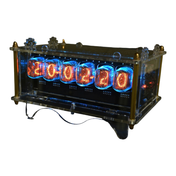
- Page 1 6-Digit Nixie Clock version 2 Assembly Manual Revision 1 – released 2020-06-02...
- Page 2 This kit is designed for someone who has intermediate experience with assembling electronics. Please take your time – it will take approximately 3 hours to complete this kit. Ensure your work area is well lit (daylight preferred) and clean. Assemble the parts in the order as stated in the instructions - read and understand each step before you perform each operation for the best chance of success.
- Page 3 Schematic and PCB Layout Main and Display Circuit...
- Page 4 Main PCB Display PCB...
- Page 5 Backlight Circuit Backlight PCB...
- Page 6 Assembling the Display PCB Mount resistors R1, R2, R4, R5, R25 and R26, 27k (red – violet – orange – gold) Mount resistors R3 and R24, 470k (yellow – violet – yellow – gold) Mount the angled pin headers K4, K6, K8, K10, K12 and K14.
- Page 7 Mounting the tubes without tube socket pins Put each IN-12 tube with its pins though the holes of the PCB from the solder side and solder them temporarily in place by soldering the top pin of each tube. Now turn over the board and take a look at the alignment of the tubes. If needed, you can still make corrections by reheating the solder connections.
- Page 8 Solder the small neon lamps LA1 and LA2 into place. The polarity doesn't matter. They shouldn't protrude as much from the PCB as the nixie tubes. The display PCB is now finished.
- Page 9 Assembling the Main PCB Mount the components from low to high. Start with the small signal schottky diodes D3 and D4, BAT46. Watch the polarity! Mount the following resistors: R27: 0,27 Ω (red – violet – silver – gold) R12, R16: 1k (brown – black – red – gold) R17: 5k6 (green –...
- Page 10 Mount the 47k/1 W resistor R28 (yellow – violet – orange – gold) and trimmer potentiometer P1 (470K). The resistor is a bit of a tight fit. Mount it so, it hovers a few millimeters above the PCB as it will get hot when the clock is powered up. Mount the ceramic capacitors C3, 470 pF and C1, C4 ...
- Page 11 Mount the bipolar transistors T1 ... T4, T8 (MPSA42) and T9 (BC557B). For esthetical reasons and to facilitate mounting, the top of the transistors should be flush with the top of the pin and socket headers. Mount the terminal block K2 and electrolytic capacitor C18 (220 μF 16 V).
- Page 12 Mount the DC/DC step-down converter module IC6 (OKI-78SR-5/1.5-W36C). The power inductor on the module should point towards K1. Mount MOSFET power transistor T5 (IRF644). Please note that this is an electrostatic sensitive device. It is recommended to touch an earthed metal object before mounting the transistor.
- Page 13 Put the Russian nixie drivers IC1 ... IC3, IC8 and IC9 (K155ID1 / 74141) in their sockets. Put PIC controller IC4 (PIC18F44K22-I/P, PIC18F45K22- I/P or PIC18F4420-I/P) in its socket. Watch the position of the notches on all ICs! Remove the GPS module from its anti static bag and put it on a flat surface.
- Page 14 Putting the PCBs together Connect the display board to the main board. You can now connect a power supply again and run a first test. After power up, the nixie tubes show the firmware version and should then cycle between digits one after each other. Note that the first nixie tube only can show numbers between 0 and 3.
- Page 15 Screw 2 plastic 8 mm standoffs to the mounting holes of the backlight board. If you are planning to put the nixie clock into the designated acrylic enclosure from Elektor, you should use two M3x16 machine screws and two nylon M3 washers to hold the standoffs in place. The M3x16 machine screws should protrude from the standoffs.
- Page 16 Wiring the clock If you are not going to use the backlight PCB, you can as well skip this step. Connect two 3 pole socket headers together using 10 cm of green, black and red wire. Insulate the solder joints using 14 mm pieces of 3.2 mm heat shrink tube.
- Page 17 You can now test your clock again if you wish to do so. The construction of the electronics of your clock has now been completed. Please read further, if you want to put the clock in the acrylic enclosure from Elektor.
-
Page 18: Assembling The Enclosure
Assembling the enclosure Disconnect the DC connector, push button and buzzer from the main PCB. Remove the protective finish from the front panel and slide it over the IN-12 nixie tubes and neon lamps of the clock assembly and attach it to the display PCB using two M3x6 machine screws. Remove the protective finish from the baseplate and the acrylic support. - Page 19 Remove the protective finish from the acrylic GPS patch antenna mounting plates. Place the antenna between the acrylic parts and screw everything together using two nylon M4x12 machine screws. Remove the protective finish from the back panel and attach the power connector using two M2x6 machine screws and two M2 nuts.
- Page 20 Remove the protective finish of the side panels. It's best to remove the small pieces of the protective finish inside engravings first and work your way from the inside to the outside of the panels. The protective finish can be a bit difficult to remove but keep in mind that it was needed to protect the acrylic from laser fumes during manufacturing.
- Page 21 For configuring and using your clock, we refer to Andy’s Nixie Clock Update: Operating instructions, which can be downloaded as a separate document.
Need help?
Do you have a question about the 6-Digit Nixie Clock version 2 and is the answer not in the manual?
Questions and answers