Table of Contents
Advertisement
Advertisement
Table of Contents

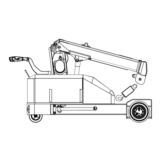
Summary of Contents for Smiley Lifting Solutions SPYDERCRANE PC094
- Page 1 Operator’s Manual SPYDERCRANE PC094 Published: July 2020...
- Page 2 Dear User, Thank you very much for choosing to use the revolutionary SPYDERCRANE PC094 Pick and Carry Crane. We highly recommend that all users undergo training in accordance with local requirements and use good sense while operating this machine. The PC094 has been designed and manufactured using the most modern techniques, procedures, and industry best practices.
-
Page 3: Table Of Contents
Reading the TS/PRC Indicator Panel • PC094 Travel and Lifting Performance Flowchart • Unapproved Uses • Technical Data (SPYDERCRANE PC094) • External Features Chapter 2: Operating Instructions • Features and Indicators of the Crane Control Group • Features of the Travel Control Group •... - Page 4 • Determining Lift Capacity of the PC094 • Returning the PC094 to Travel Mode • Hoisting and Transporting the PC094 Chapter 3: Troubleshooting • Crane Controls are Unresponsive AND Percent Rated Load Indicator is RED 66 • Crane Does Not Travel •...
-
Page 5: Chapter 1: General Information
Chapter 1 GENERAL INFORMATION... -
Page 6: Scope
This manual MUST stay with the PC094, or be otherwise immediately accessible to anyone who requires information on the PC094. • If the SPYDERCRANE PC094 is sold, the User’s Manual and its corresponding literature MUST accompany the crane. • The information within this manual is subject to modification by Smiley Lifting... -
Page 7: Using This Manual
Dangers are identified by a red-bordered text box with a DANGER symbol. WARNING Warnings • These are hazards that can cause bodily injury and/or damage, or complete destruction, of the SPYDERCRANE PC094 and/or its attached load. • Warnings/Cautions are identified by an orange-bordered text box with a WARNING symbol. -
Page 8: Dangers
GENERAL INFORMATION Dangers High Voltage Power Lines A danger, even if not directly contacted. NEVER operate the SPYDERCRANE PC094 or handle a load near electric lines. Maintain a minimum clearance distance from energized power lines in accordance with applicable regulations. Moving Parts The PC094 has multiple moving parts that can cause serious injury. -
Page 9: Warnings
ALWAYS wear personal protective equipment when operating the PC094. • ALWAYS review the safety instructions before using the PC094. • ALWAYS perform a safety inspection of the SPYDERCRANE PC094 before using it. Lifting with the PC094 • NEVER use the PC094 to lift personnel. -
Page 10: Personnel Definitions
PC094 should be permitted to operate, maintain, or work with the PC094. SPYDERCRANE Training Smiley Lifting Solutions, as the manufacturer and distributor of the PC094, offers PC094 Operator, PC094 Maintainer, and Train-the-Trainer programs. -
Page 11: General Description Of The Pc094
What the PC094 IS NOT The SPYDERCRANE PC094 IS NOT designed for off-road or all-terrain use. The PC094 has very limited travel angle (surface grade) limits and its use should be limited to spaces with leveled and improved surfaces. -
Page 12: Exterior Placards And Signage
GENERAL INFORMATION Signage Installed to the SPYDERCRANE PC094 DANGER, Electrocution Hazard DANGER, Pinch Point CAUTION, Foot Crush Hazard CAUTION, Rated Load and Max Capacity CAUTION, Rated Load and Rated Load Chart CAUTION, Lift Point Location and Rigging Instructions CAUTION, Travel Angle Limits... - Page 13 1,900 lbs 1-Part Hook...
-
Page 15: Theory Of Operation
Theory of Operation Electrical Power The SPYDERCRANE PC094 is powered by its Battery Array. The PC094 Battery Array includes four Lifeline GPL-4DL Absorbent Glass Mat (AGM) batteries, arrayed into two banks, one on either side of the PC094’s carrier. The battery array is managed by an onboard charging and maintenance system. -
Page 16: Operator Aids
GENERAL INFORMATION Operator Aids Anti-Two-Block System The Anti-Two-Block (A2B) System is designed to prevent the Operator from damaging the PC094 by allowing the hook block to impact the boom tip of the PC094. Without the A2B System, if the PC094 Operator WINCHES UP, or if the operator BOOMS OUT without WINCHING DOWN, the hook block will rise until it impacts the tip of the PC094’s boom, possibly causing damage. - Page 17 profiles depending on the PC094’s Boom Stage and Stabilizer status (STORED/ EXTENDED): The Heavy-Weight (HW) Profile is indexed when the Stabilizers are EXTENDED, and the Boom Stage is 1 OR 2. The Medium-Weight (MW) Profile is indexed when the Stabilizers are STORED, and the Boom Stage is 1 OR 2.
- Page 18 Stabilizers Stored Switch The Stabilizers Stored Switch is a limit switch that is OPENED when BOTH Stabilizers have been rotated and locked into their stored conditions. The Stabilizers Stored Switch has three functions, as it applies to lifting or traveling with the PC094: •...
- Page 19 Travel Speed Indicator (TSI) The Travel Speed Indicator (TSI) is a three-color LED, viewable from the Operator’s Station that is used to indicate the maximum available travel speed of the PC094. • When the TSI is GREEN, the PC094 can be traveled at 100% available speed (the PRCI will light up in RED).
-
Page 20: Pc094 Travel And Lifting Performance Table
GENERAL INFORMATION PC094 Travel and Lifting Performance Table Indexed Travel Speed Percent of Rated Percent Boom Stabilizers Boom Travel Lifting Indicator Capacity Indicator of Rated Lifting Stored Stored Stage Speed Profile (TSI) (PRCI) Capacity Stored Stored Green 100% 100% Working Stored 1,2,3 Medium... -
Page 21: Pc094 Travel And Lifting Performance Flowchart
GENERAL INFORMATION PC094 Travel and Lifting Performance Flowchart... -
Page 22: Unapproved Uses
GENERAL INFORMATION Unapproved Uses of the SPYDERCRANE PC094 The SPYDERCRANE PC094 should ONLY be used by personnel that have been fully trained to operate, or maintain, it. The instructions for safe and proper use are fully contained within this User’s Manual. -
Page 23: Technical Data (Spydercrane Pc094)
GENERAL INFORMATION Technical Data (SPYDERCRANE PC094) Model PC094 Serial Number Maximum Rated Load 1,900 pounds Total Weight with Batteries 2,900 pounds Weight on Front Wheels (unloaded) 1,125 pounds Weight on Rear Wheels (unloaded) 1,775 pounds Ground Pressure on Front Wheels (unloaded) - Page 24 GENERAL INFORMATION Technical Data (PC094 Battery Array) Per Battery (Lifeline GPL-4DL) Volts Length (per battery) 20.76 in Width (per battery) 8.7 in Height (per battery) 8.64 in Weight (per battery) 124 lbs 1595 (@68° F) Cold Cranking Amps 1360 (@32° F) 1100 (@0°...
-
Page 25: External Features
GENERAL INFORMATION The External Features of the PC094 Right-Side (Travel Mode) PC094, Right-Side, with callouts Tiller Handle Lift Cylinder Tiller Tie-Back/Rear Tie-Down Point (right-side) Winch Gear Box Right Drive Wheel Lift Point (right-side) Right Stabilizer Release Lever Boom Tip... - Page 26 GENERAL INFORMATION The External Features of the PC094 Right-Side (Travel Mode) The part of the Tiller that the operator handles while Tiller Handle traveling the PC094. The Tiller can be rotated and locked into the Travel setting or Crane Mode setting. The control arm that is connected to the Steering Wheel of Tiller the PC094.
- Page 27 GENERAL INFORMATION The External Features of the PC094 Left-Side (Travel Mode) Sheave Pin 1-Part Hook Block Lift Point (left-side) Tie-Back/Rear Tie-Down Point (left-side) Hinge Pin Left Stabilizer Crane Control Levers (3) Left Drive Wheel Wire Rope Drum (exposed) Idle/Steering Wheel...
- Page 28 GENERAL INFORMATION The External Features of the PC094 Left-Side (Travel Mode) The large-diameter pin that holds the boom tip sheave which guides the wire rope from the wire rope drum to the Sheave Pin hook block. The sheave pin is also used to measure boom length and boom tip height.
- Page 29 GENERAL INFORMATION The External Features of the PC094 Front (Travel Mode, Boom raised to 0°, Hook Block removed) Lift Point (right-side) Front Tie-Down Point (right-side) Lift Point (left-side) Front Tie-Down Point (left-side) Winch Gear Box Right Drive Wheel Minimum Wire Rope Safety Left Drive Wheel Hook Storage Shackle...
- Page 30 GENERAL INFORMATION The External Features of the PC094 Front (Travel Mode, Boom raised to 0°, Hook Block removed) One of the two steel rings welded to the boom of the PC094, at its horizontal center-of-gravity. Properly rigged, Lift Point (right-side) the PC094 can be lifted by another lifting system at the Lift Points.
- Page 31 GENERAL INFORMATION The External Features of the PC094 Rear, Travel Mode Travel Control Group/ Tiller Handle Tie-Back/Rear Tie-Down Point (left-side) Crane Control Group Tie-Back/Rear Tie-Down Point (right-side) Hydraulic filter (inside) Idle/Steering Wheel Fuse box (inside)
- Page 32 GENERAL INFORMATION The External Features of the PC094 Rear, Travel Mode The controls used to travel the PC094 when it is running. Travel Control Group The Travel Control Group is located at the end of the Tiller Handle. The Crane Control Group is the collective of controls and indicators that are used to turn the PC094 on and off, Crane Control Group control the crane functions, charge the battery array, or...
- Page 33 GENERAL INFORMATION The External Features of the PC094 Hood, Storage Compartment, Hydraulic Oil Tank, and Hook Block Storage The Hydraulic Oil Tank and Storage Compartment and stored 1-Part Hook Block. The Hood of the PC094 has been opened and made transparent. Hood (opened and transparent) Hydraulic Oil Tank (with cap) Storage Cup with stored 1-Part Hook Block...
- Page 34 GENERAL INFORMATION The External Features of the PC094 Hood, Storage Compartment, Hydraulic Oil Tank, and Hook Block Storage The fiberglass hood of the PC094 covers and protects the Hood (opened and transparent) Hydraulic Oil Tank, Hook Storage Cup, and Storage Compartment.
- Page 35 Chapter 2 OPERATOR INSTRUCTIONS...
-
Page 36: Chapter 2: Operating Instructions
Features and Indicators of the Crane Control Group The Crane Control Group All of the controls and indicators used to start and use the crane functions of the SPYDERCRANE PC094 are located within the Crane Control Group (CCG). Battery Level Indicator Winch Control Lever... - Page 37 Operating Instructions Features and Indicators of the Crane Control Group These are the controls and indicators within the Crane Control Group (CCG), organized from left-to-right. 1. Battery Level Indicator The Battery Level Indicator displays the charge level of the PC094 Battery Array when the PC094 is powered-on and NOT plugged in.
- Page 38 Insert the key when starting the PC094 for use. To activate the Safety Override Switch, rotate the key clockwise and hold it to disable ALL of the PC094’s The Safety Bypass Switch with no key safeties and operator aids. inserted (left), with key inserted and OFF (middle), and held in the ON 4.
- Page 39 To charge the PC094 from a conventional three-prong- compatible outlet, lift the weather-cap and plug in the female end of an appropriate extension cord and then plug in the male-end into the outlet. 9. Runtime Meter The Runtime Meter indicates the number of hours and tenths of hours that the PC094 has been run over its lifetime.
- Page 40 Maximum charge-rate is indicated by the orange LED next to the six hash marks, minimum charge- rate is indicated by the orange LED next to the single hash mark. If the orange LED is solid, the charge-rate is determined solely by the charge status of the battery array.
-
Page 41: Features Of The Travel Control Group
Operating Instructions Features of the Travel Control Group The Travel Control Group (TCG) All of the controls and indicators used to travel the SPYDERCRANE PC094. Tiller (not fully pictured) Safety Horn Button Tiller Handle Pin Auto-Forward Switch Tiller Handle (Gray-colored portion) - Page 42 Operating Instructions Features of the Travel Control Group These are the controls and indicators within the Travel Control Group (TCG), organized from front-to-back. 1. Tiller The Tiller is the long lever that is connected to the Steering Wheel of the SPYDER- CRANE PC094.
- Page 43 The Accelerator is used to control the direction and speed of the PC094’s two Drive Wheels. The Accelerator is a spring-loaded controller designed to be operated with the thumbs. The two switches (left and right) of the Accelerator are linked together, if the left switch is rolled forward, the right switch will also roll forward.
-
Page 44: Charging The Pc094
Operating Instructions Charging the PC094 The SPYDERCRANE PC094 can be charged from a normal 120V outlet with some conditions: • The outlet MUST be capable of accepting a 3-Prong extension cord • The outlet must be properly grounded and include a fuse/circuit breaker rated for NO LESS than 15A •... -
Page 45: Shift Inspection Of The Pc094
3. The load should remain suspended for 3 full minutes. 4. Lower the load. If any deficiencies are found, DO NOT USE THE CRANE until the crane has been fixed. Contact Smiley Lifting Solutions Service Department for assistance. Smiley Lifting Solutions 5326 West Mohave Street... -
Page 46: Starting And Stopping The Pc094
The SPYDERCRANE PC094 should never be powered-off and un- attended while it has an attached load. • If the SPYDERCRANE PC094 must be powered-off while a load is attached at the hook block; the load should be lowered to the ground. -
Page 47: The Operating Modes Of The Pc094
Operating Instructions The Operating Modes of the PC094 Both the traveling and lifting performance of the SPYDERCRANE PC094 are greatly effected by its Operating Mode. When the PC094 is configured for traveling WITHOUT a load it is configured to Travel Mode... - Page 48 Pick-and-Carry Mode To move the PC094 with an attached load, the PC094 Operator will use the Pick-and- Carry (PC) Mode. In PC Mode, the boom and hook block are out of their stored conditions and a load is being carried by the PC094. In PC Mode, the maximum travel speed of the PC094 is automatically limited, based on the length of the boom, whether the Stabilizers have been extended, and the weight of the attached load.
-
Page 49: Traveling The Pc094 In Travel Mode
Operating Instructions Traveling the PC094 In Travel Mode • Start the PC094 after confirming that it is Travel Mode (no attached load; boom, hook block, and stabilizers stored). • Place the Tiller Handle into its Travel Position. • Sound the Safety Horn to warn bystanders that the PC094 will be moving. •... -
Page 50: Switching The Pc094 From Travel Mode To Crane Mode
Operating Instructions Switching the PC094 from Travel Mode to PC Mode When you are ready to use the PC094 for lifting and traveling, you will need to re-configure it from Travel Mode to PC Mode. In Travel Mode, the PC094’s boom, hook block, and stabilizers are in their stored positions. -
Page 51: Attaching And Lifting A Load
Operating Instructions Attaching and Lifting a Load 1. Securely attach proper rigging to the grounded load 2. Maneuver the PC094 as close as possible to the grounded load, making sure not to overrun the load so that it gets caught on the carrier of the PC094 when it is attached and lifted 3. -
Page 52: Traveling The Pc094 With An Attached Load
Operating Instructions Traveling the PC094 with an Attached Load 1. Confirm that the attached load is raised off the ground. Optional: brace the load against the fenders to prevent sway. 2. If required, confirm the stabilizers are extended and locked. 3. -
Page 53: Using The Stabilizers Of The Pc094
Operating Instructions Using the Stabilizers of the PC094 The stabilizers of the PC094 are used to increase its surface footprint along its short axis. In short, the stabilizers help to stabilize the PC094 in PC Mode. While not required if hauling relatively light loads (and using the Light-Weight or Medium-Weight Lifting Profiles), it is a good technique to extend the stabilizers EVERY TIME you are operating the PC094 in PC Mode with an attached load. -
Page 54: Traveling The Pc094 In Inclined Surfaces
Operating Instructions Traveling the PC094 on Inclined Surfaces WARNING Travel Angle Limits NEVER EXCEED the Travel Angle Limits of your PC094, especially with an attached load While the SPYDERCRANE is designed to be traveled over flat surfaces, it is capable of being safely traveled over inclined surfaces, with certain limits and conditions: Travel Angle Limits Travel Angle Limits refer to the MAXIMUM angle of the inclined surface that the PC094 can... - Page 55 Operating Instructions WARNING Approaching Inclined Surfaces • • NEVER attempt to travel onto an inclined surface at anything other than a 90-degree angle (“straight-on”) • Traveling onto an inclined surface while the PC094 is at an acute (less than 90-degree) angle WILL de-stabilize the PC094 and result in a tip over Proper PC094 Alignment for Traveling on Inclined Surfaces When traveling onto inclined surfaces, ALWAYS approach the inclined surface straight-...
-
Page 56: Lifting Profiles And Pc Mode
Operating Instructions Lifting Profiles and PC Mode The SPYDERCRANE PC094’s Maximum Rated Load Capacity is influenced by the indexed Lifting Profile. The PC094 has three separate Lifting Profiles, and it indexes a specific based on how the PC094 is configured, while in PC Mode: •... -
Page 57: Determining Lift Capacity Of The Pc094
Operating Instructions Determining Lift Capacity of the PC094 Determine the Boom Stage for the PC094 The boom of the PC094 is composed four telescoping sections. Boom Section One is the larg- est section and it connects to the turret of the PC094 at the Hinge Pin and Lift Cylinder. Sec- tion Two nests inside of Section One until it is telescoped out. - Page 58 Operating Instructions Determining Lift Capacity of the PC094 Determine the Working Radius for the PC094 Working Radius is the horizontal distance between the Front Wheel Center and Hook Center of a crane. Working radius is used to determine how much a crane can safely lift, the greater the working radius, the LESS the crane can lift (usually).
- Page 59 Operating Instructions Determining Lift Capacity of the PC094 Using the Boom Angle Indicator Installed one each side of Boom Section One of the PC094 is the Boom Angle Indicator. The Boom Angle Indicator is a manual lift planning aid that the operator uses to calculate the PC094’s boom angle and working radius.
- Page 60 Operating Instructions Determining Lift Capacity of the PC094 Using the Boom Angle Indicator Below are some examples of PC094’s with different boom angles and boom stages, which re- sult in different working radii. When the boom is in Stage 1 and lowered to Boom Angle -10°...
- Page 61 Operating Instructions Determining Lift Capacity of the PC094 Using the Rated Load Chart After you have determined the PC094’s working radius and boom stage, you can use the Rat- ed Load Chart to figure out how much the PC094 can safely lift. 1.
-
Page 62: Returning The Pc094 To Travel Mode
Operating Instructions Returning the PC094 to Travel Mode 1. BOOM IN to Stage 1, WINCHING UP to prevent the hook block from dragging on the ground. • The boom is properly stored when the TS/PRC Indicator Panel has TWO green lights. 2. -
Page 63: Hoisting And Transporting The Pc094
Operating Instructions Hoisting and Transporting the PC094 Rigging for Hoisting 1. Confirm that the PC094 is in Travel Mode (with the hook block attached to the Storage Shackle) and that stabilizers are stored. 2. Rotate the Tiller Handle to Crane Mode. 3. - Page 64 Operating Instructions Hoisting and Transporting the PC094 Rigging for Transport 1. Confirm that the PC094 is in Travel Mode and that stabilizers are stored. 2. Rotate the Tiller Handle to Crane Mode. 3. Attach shackles rated for AT LEAST 3,000 lbs. to each of the four tie-down points of the PC094.
-
Page 65: Chapter 3 Troubleshooting
Chapter 3 TROUBLESHOOTING... -
Page 66: Crane Controls Are Unresponsive And Percent Rated Load Indicator Is Red
Troubleshooting Crane Controls are Unresponsive AND Percent Rated Load Indicator is... -
Page 67: Crane Does Not Travel
Troubleshooting Crane Does Not Travel... -
Page 68: Crane Does Not Turn
Troubleshooting Crane Does Not Turn... -
Page 69: No Hydraulic Response
Troubleshooting No Hydraulic Response... -
Page 70: Chapter 4: Preventative Maintenance
Chapter 4 PREVENTATIVE MAINTENANCE... -
Page 71: Introduction
Preventative Maintenance Introduction Proper lubrication and maintenance are essential to ensure long life and good working conditions for the PC094. The parts to be checked and greased as well as the fluid levels to be maintained are described below. Operating time depends on the duty cycle, environmental and operating conditions (humidity, temperature, salty air, conditions of the ground, etc.) where the crane is working. -
Page 72: Maintenance Intervals And Lubricants
Preventative Maintenance Maintenance Intervals and Lubricants Part Recommended Fluid/Lubricant Maintenance Interval Grease Fittings Molybdenum Grease Every 40 hours of operation or 3 months NLGI No. 2 in most cases NLGI No. 1 in very cold climates Boom Molybdenum Grease Every 40 hours of operation or 3 months NLGI No. -
Page 73: Grease Fittings
Grease Fittings 1. Wire rope winch drum 2. Boom Lift Cylinder Upper Pivot 3. Boom Lift Cylinder Lower Pivot (requires removing the side panels) 4. Boom Hinge Pin 5. Steering Shaft 6. Steering Pivot Bearing Boom Grease 1. Completely extend the boom 2. -
Page 74: Wear Pad Replacement
Wear Pad Replacement 1. Place the boom at 0° 2. Extend the boom completely. 3. Loosen the retaining bolts on the top of the boom section. 4. Lower the boom tip onto an outrigger pad until there is a small space above the wear pad. -
Page 75: Drive Wheel Gear Oil Replacement
Drive Wheel Gear Oil Replacement 1. Orient the drive wheel so that the larger of the two ports is at the bottom and the smaller is at the top right. 2. Place a catch container capable of holding at least 0.5 gallons under the drive wheel gear. -
Page 76: Chapter 5: Warranty Information
Chapter 5 WARRANTY INFORMATION... -
Page 77: Spydercrane Product Warranty
SPYDERCRANE Product Warranty SPYDERCRANE mini-cranes shall not be covered by any other warranty, expressed or implied, made by SPYDERCRANE or distributors of this product, except this warranty against defects in material and workmanship of new products, as hereinafter set forth. The warranty period on all SPYDERCRANE mini-cranes in 12 months or 1,500 hours from the original date of purchase, lease or rental and is available only to the original purchaser of the product. - Page 78 Under no circumstances shall SPYDERCRANE be liable for any consequential or special damages which any person or entity may incur or claim to incur as a result of any defect in its product. This includes, but is not limited to: the cost of transportation; lost sales, orders, profits, and income; increased overhead, labor and materials.
- Page 79 completing the warranty repair. Use of non-approved parts is not acceptable and may void all warranties. Approved parts for warranty repairs may be from inventory or ordered from SPYDERCRANE. All warranty replacement parts will be shipped via ground freight, F.O. B. SPYDERCRANE, and invoiced like standard parts orders.
Need help?
Do you have a question about the SPYDERCRANE PC094 and is the answer not in the manual?
Questions and answers