Table of Contents
Advertisement
Quick Links
Introduction
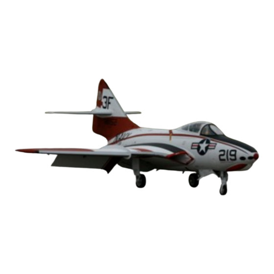
Der Jet F9F-8 Cougar
Manual Version 3.0
Changes in version 3.0 include new strut door attachments, new parts pic-
tures and addendums on the nose strut, fuel system plumbing and speed
brake hinges.
Specifications:
•
Length: 84 inches
•
Wingspan: 70 inches
•
Height: 29 inches
•
Weight: 30-34 pounds
•
Fuel Capacity: 5 Liters (170 ounces)
•
Turbine: 24-36 pounds
Der Jet F9F-8 Cougar
Contents of Manual:
Introduction
•
History of F9F-8 Cougar
•
Kit Features
•
Tools
•
Glues
•
General Preliminary Planning
Construction
•
Page 6: Horizontal and Vertical Stabs
•
Page 16: Air Systems
•
Page 29: Fuel Systems
•
Page 31: Split Flaps
•
Page 33: Pipe and Engine
•
Page 35: Wings
•
Page 37: Receiver and Batteries
•
Page 38: Cockpit
•
Page 39: Nose Cone
•
Page 39: Scale Details
•
Page 41: Preparing for Flight
Appendices
•
A: Suggested Equipment Layout
•
B: Test Flying your Cougar
•
C: Maintenance and Addendum's
•
D: Parts Photos
Page 1
Advertisement
Table of Contents

Related Manuals for Der Jet Model F9F-8 Cougar

Summary of Contents for Der Jet Model F9F-8 Cougar
- Page 1 Introduction Contents of Manual: Introduction • History of F9F-8 Cougar • Kit Features • Tools • Glues • General Preliminary Planning Construction • Page 6: Horizontal and Vertical Stabs • Page 16: Air Systems • Page 29: Fuel Systems •...
- Page 2 However, with the capability of carrying two Sidewinder infrared- the F9F-8 Cougar was rapidly made obsolete by newer homing air-to-air missile underneath each wing. This fea- supersonic designs that began to enter service in the late ture was retrofitted to many earlier F9F-8s.
- Page 3 Painted out of the mold, with a full complement of detailed nomenclature There are two primary glues you will utilize in the con- • Scale antenna and nose gear parts struction of your Der Jet model. • Twin carbon fiber spars • 5 liter fuel capacity •...
- Page 4 With a fuel capacity of 5 liters and an exit pipe diameter of tended. There are several choices for gear actuation: 80 mm, the Cougar may handle slightly larger engines while providing acceptable flight times, as long as top Der Jet F9F-8 Cougar Page 4...
- Page 5 This provides a short servo Note: the servo extensions are run as the construction run to the receiver. progresses. • Length of servo extensions will be determined by the final location of your receiver. Der Jet F9F-8 Cougar Page 5...
- Page 6 Using a scrap piece of ply approximately 3/16 x 1.25 x 1, create a backing plate for the JR 3421 servo. Do not glue in place yet. Above: Ply backing plate for servo Left: Stab as it comes from the factory Der Jet F9F-8 Cougar Page 6...
- Page 7 Add small blocks made from scrap wood fore and aft of the servo to prevent lateral play. Above: Small wooden blocks fore and aft capture servo. Left: 1/16 inch cutter bit in Dremel tool routing servo wire hole Der Jet F9F-8 Cougar Page 7...
- Page 8 Mark lateral location of servo arm on plate. Reposition cover to the left to tured in all three axis by the ply backer, wood blocks and servo cover. mark for fore and aft measurements. Der Jet F9F-8 Cougar Page 8...
- Page 9 T square to keep the line perpendicular to the hinge line. With clevis hole on hinge line, mark fore and aft extents of control arm. Der Jet F9F-8 Cougar Page 9...
- Page 10 Make sure the vertical position of the servo arm is identical on both elevators. Throw should be right at 30 mm, measured at the in- ner end of the elevator. Stab is now complete and ready for mounting. Der Jet F9F-8 Cougar Page 10...
- Page 11 Mark location of control arm on the U bracket so it is soldering, you may also solder the control horn to the centered in the middle of the access area. U bracket with aluminum solder paste or JB Weld. Der Jet F9F-8 Cougar Page 11...
- Page 12 At this point, do not get any glue on the tops of the clamp nuts. hardwood strips, as the servo ply mounting plate needs to sit down flush on the strips. Der Jet F9F-8 Cougar Page 12...
- Page 13 U bracket will affect the re- Add rudders and recheck fit. When satisfied, inject a quired length of the pushrods. generous amount of V-poxy into the hinge point holes Der Jet F9F-8 Cougar Page 13...
- Page 14 You can make a trip to the hardware store for a longer saddle. You may need to relieve front of saddle bolt or drill the front spar with a #36 drill and tap for a slightly to achieve a perfect fit. Der Jet F9F-8 Cougar Page 14...
- Page 15 Attach tail cone with small wood screws, two per side. These screws were left over from the horizontal stabilizer cover plates, which were attached with heavy duty button screws as outlined in the instructions. Der Jet F9F-8 Cougar Page 15...
-
Page 16: Air Systems
fit. Note that you will need to rout a small slot for the gear with your hand pump. If there is any binding, the air line that exits the side of the retract unit, and Der Jet F9F-8 Cougar Page 16... - Page 17 Make up linkage arms. Center the servo using your Matchmaker, install servo arm and linkages to the servo. Add air lines to nose retract unit and check for proper operation and leaks. Der Jet F9F-8 Cougar Page 17...
- Page 18 Apply a generous amount of V-poxy into each slot. A Location of main door bracket slot 20 mm down from lip. Tape prior to glue nozzle really helps for this type of glue work. gluing. Der Jet F9F-8 Cougar Page 18...
- Page 19 Clamp in place and allow the CA to dry completely. Attach the cylinder to the aft side of the wooden L Run a bead of V-poxy around the brackets to secure. bracket, with the tab facing away from the cylinder. Der Jet F9F-8 Cougar Page 19...
- Page 20 Make sure there are no kinks. Completed installation. Note cylinder is attached to the back side of wooden L bracket. Tab is positioned against front of wheel well. Completed main door cylinder Der Jet F9F-8 Cougar Page 20...
- Page 21 Drill and tap the aluminum bracket as shown. Install 2-56 ball link. Paint aluminum bracket white to match the strut if desired. Position top of aluminum bracket 40 mm from the top of the strut. Der Jet F9F-8 Cougar Page 21...
- Page 22 Pencil mark the center position of the ball link on the edge of the door with the strut extended. This is mark 1. Strut door block. The bevel is for appearance. Make sure hight is no more than 7 mm. Der Jet F9F-8 Cougar Page 22...
- Page 23 Completed door strut installation, showing linkage and location of strut block on the door. The vertical location of the center of the strut block on the door will align with a point half way between the two marks. Der Jet F9F-8 Cougar Page 23...
- Page 24 You will need to notch the aft two formers to clear the cylinder retaining pin. The tail hook assembly should have two small retain- ing holes drilled in the end of the aluminum assembly. Der Jet F9F-8 Cougar Page 24...
- Page 25 If you will mount with a #2 button screw, drill the ends Protect air lines from tail hook with heat shield braid or aluminum tape. with a #46 bit. Securely affix to fuselage. Der Jet F9F-8 Cougar Page 25...
- Page 26 Using a grinder bit in a 90 degree attachment for the Dremel, rout a slot for the speed brake hinges. You may need to temporarily undo the nose door cylinders to open up the doors fully for access. Der Jet F9F-8 Cougar Page 26...
- Page 27 Mark and drill two holes per hinge from the bottom of Operate the cylinders using your hand pump to make the fuselage into the hinges and secure with small sure they open and close fully. screws. Der Jet F9F-8 Cougar Page 27...
- Page 28 The suggested layout of the main board and air sys- There are many brake valve options available. On the tems board are shown in Appendix B. Run all air lines prototype, a BVM smooth stop was used. and test the various systems. Der Jet F9F-8 Cougar Page 28...
-
Page 29: Fuel System
Upper tank can be held in place with velcro, wire, or The clunk assembly. Safety wire all connections before installing. as shown here, carbon fiber cord. The cord loops around the tank and attaches to the air board. Der Jet F9F-8 Cougar Page 29... - Page 30 Finally, run a vent line. See photo for location of fuel Plumbing installed on tanks. Note loop from main tank pickup to UAT to vent on prototype. Wire tie. avoid kinks. Pickup tubes must be splayed slightly to allow UAT to fit. Der Jet F9F-8 Cougar Page 30...
- Page 31 Rough gluing surface on control arm, tape area around slot, apply a very liberal amount of V-poxy into the slot and position arm vertically. Mark location of control arm from inside the fuselage. See text. Der Jet F9F-8 Cougar Page 31...
- Page 32 fiber or brass sheath as shown in the photo. Connect linkage and enlarge hole as needed. Split flap linkage installed. Shown in fully deployed position. Force of flap will act in a lineal fashion on the servo sprocket, reducing current load. Der Jet F9F-8 Cougar Page 32...
- Page 33 Cut two pieces of 1/4 inch ply 50 mm x 15 mm. Screw pieces of wood to pipe tail flanges. Using two pair of pliers, twist the mounting tabs 90 degrees. Pipe mount strap showing twist and 3/16” ply spacer beneath. Der Jet F9F-8 Cougar Page 33...
- Page 34 In the prototype kit, engine compo- nents were installed in the nose of the aircraft. Ulti- mately, this will help reduce or eliminate the need for ballast. Engine component layout in nose of aircraft. Der Jet F9F-8 Cougar Page 34...
-
Page 35: Wing Construction
You will also need to grind the screws down until they don't protrude from the back of the bracket. Use Loctite. Servos are attached to aluminum brackets. Make sure screws are cut off flush with back of bracket. Der Jet F9F-8 Cougar Page 35... - Page 36 CA to the end to the threads. As you did with the elevator linkages, mark the posi- tion of the control arms, allowing for the offset of the linkage ball ends. Grind slots. Servo positioned in pocket. Note SWB arm. Der Jet F9F-8 Cougar Page 36...
- Page 37 Location of twin receiver batteries and ECU battery. Keep the batteries in the nose to avoid the need to add ballast when determining CG. Wing is now finished. Dubro Heavy Duty ball links required when using SWB arms to accommodate 4-40 bolt for arm. Der Jet F9F-8 Cougar Page 37...
- Page 38 You will likely need to trim a little of the forward cockpit rails to slide cockpit past fuel tank on an angle. With cockpit in place, drill and secure with 4 flat head screws. Cockpit position. Note use of 4 flat headed screws for attachment. Der Jet F9F-8 Cougar Page 38...
-
Page 39: Scale Details
If desired, simulate air holes on speed brakes with small black vinyl dots. As the door is hollow, it is not recommended that you actually drill out the speed brake holes. Location of nose cone retaining bolt. Nose spring attached to strut. Der Jet F9F-8 Cougar Page 39... - Page 40 Construction Manual Antenna on starboard door. Congratulations! This completes the basic construction of your model. Der Jet F9F-8 Cougar Page 40...
-
Page 41: Preparing For Flight
A good place to start CG is at the aft side of the for- ward carbon fiber spar with residual fuel and gear down. An easy way to check CG is to set the model on a low stand with the wings away from the fuse just Der Jet F9F-8 Cougar Page 41... -
Page 42: Appendix A: Equipment Installation
Appendix A: Equipment Installation The completed air board. Air board aft of fuel tank. Air board with tank in place. Forward tank retainer. DerJet F9F-8 Cougar Page 42... - Page 43 Appendix A: Equipment Installation Mainboard with easy access to air fill systems, receiver and fill valves. Fuel Engine components mounted in nose. and gas fill seen just to the right The completed Cougar Battery installation in nose. DerJet F9F-8 Cougar Page 43...
-
Page 44: Appendix B: Test Flying Your Cougar
All in all, I find re-trim elevator for approach speed. When set, it takes 6-10 flights to fully explore the airplane and lock momentarily increase the throttle to full, counting the down all the settings. DerJet F9F-8 Cougar Page 44... -
Page 45: Appendix C: Ongoing Inspections And Maintenance
Do not fly if any of these Ridge filed down to provide a smoother transition from locked position conditions are found. DerJet F9F-8 Cougar Page 45... - Page 46 Upper Nose Strut: Older kits have a nose gear upper strut that measures 43 mm. A new upper strut is avail- able that measures 48 mm. Please contact your distribu- tor if you have the shorter upper nose gear strut for a re- placement. DerJet F9F-8 Cougar Page 46...
-
Page 47: Appendix D: Parts Photos
Appendix D: Parts Photos Note: Manufacturer may elect to update parts from time to time. Please consult your kit distributor with questions pertaining to differences. DerJet F9F-8 Cougar Page 47...
Need help?
Do you have a question about the F9F-8 Cougar and is the answer not in the manual?
Questions and answers