
Related Manuals for EMAC SoM-250ES

Summary of Contents for EMAC SoM-250ES
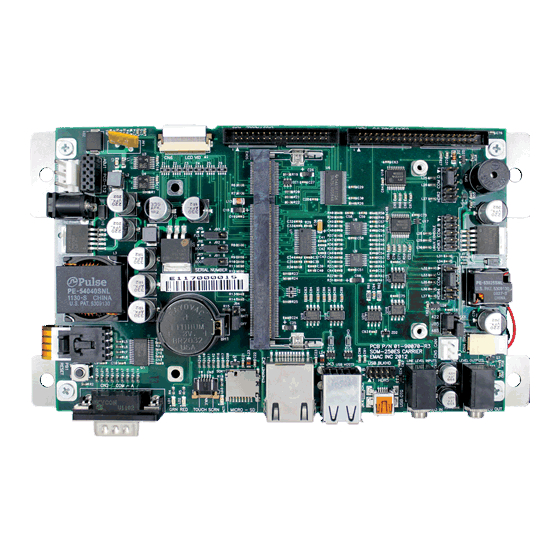
- Page 1 SoM-250ES SoM 200-pin Carrier Board User Manual REV. 1.4 Copyright 2014 EMAC, Inc.
-
Page 2: Table Of Contents
Table of Contents Disclaimer ..............................1 SoM-250 Product Summary ......................2 Specifications ................................3 SoM-250 Product Details ........................4 Jumper Configuration & Connector Descriptions ......................4 Power Connectors ................................ 5 Ethernet ..................................5 CAN Port ..................................5 Serial Ports ................................... 5 USB Host Ports ................................ -
Page 3: Disclaimer
Disclaimer EMAC Inc. does not assume any liability arising out of the application or use of any of its products or designs. Products designed or distributed by EMAC Inc. are not intended for, or authorized to be used in, applications such as life support systems or for any other use in which the failure of the product could potentially result in personal injury, death or property damage. -
Page 4: Som-250 Product Summary
800 x 480 (WVGA) or 1024 x 600 (WSVGA) LCD with LED Backlight • Touchscreen Interface and Software Controlled Backlight On/Off & Brightness • FREE Qt Creator IDE with GCC & GDB development tools SoM-250ES_User_Manual_v1.40.doc Rev 1.4 © 2014 EMAC, Inc. -
Page 5: Specifications
Specifications LCD – 7” LCD (SoM-250ES-000) • Display Type: 7" TFT Color LCD • Resolution: 800 x 480 WVGA @ 256K Colors • Dot pitch: 0.19mm x 0.19mm • Luminance: 330 (cd/m²) • Viewing Angle: 55° • Brightness: Software controlled •... -
Page 6: Som-250 Product Details
HDR4 Serial Port COM C HDR5 Bulkhead USB Connector Port A & B HDR6 LVDS & Touch Signal Connector SOK1 MicroSD Card Socket SOK2 200 pin SOM Socket ABJ1 PCD-E12 Expansion Module Connector SoM-250ES_User_Manual_v1.40.doc Rev 1.4 © 2014 EMAC, Inc. -
Page 7: Power Connectors
2.1mm with a center V+ connection. This jack allows for easy connection to a wall mount power supply (EMAC part number PER-PWR-00035). The SOM-250’s power input uses a switching regulator and allows a voltage input of +12V DC to +26V DC. - Page 8 232 RX, 422/485 TX+ 232 RX, 422/485 TX+ 232 TX, 422/485 RX+ 422/485 RX- 232 TX, 422/485 RX+ 422/485 RX- Table 4 (COM D Pinout) Pin Description for 10- Pin Description for DB9 Pin Header Connector SoM-250ES_User_Manual_v1.40.doc Rev 1.4 © 2014 EMAC, Inc.
-
Page 9: Usb Host Ports
USB Host Ports The SoM-250 provides one dual USB 2.0 (USB Port A & B) high speed host port (JK3). USB PortA and PortB can be accessed from the bulkhead connector (HDR5). EMAC can provide a cable (CAB-40-004) to access these ports. -
Page 10: I/O Expansion
RTC are included in the operating systems. Jumper JB4 should be placed in the ON position in order to retain system time when powered down. 2.13 Reset The SoM-250 provides a Reset Button (PB1). Pressing this button will cause the system to reset. SoM-250ES_User_Manual_v1.40.doc Rev 1.4 © 2014 EMAC, Inc. -
Page 11: Software
Linux. For more information on these particular Operating Systems, contact EMAC, Inc. For more information on Software, see the module’s User’s Manual. Note: All of the links in this document are subject to change. Please contact EMAC for updated link locations if necessary. -
Page 12: Appendix A: Connector Pinouts
USB_Data+ USB_ID 4.2.3 PortA/B (HDR5) Signal Signal USB_PWR_A USB_PWR_B USB_HOSTA- USB_HOSTB- USB_HOSTA+ USB_HOSTB+ Chassis GND Power Jack (JK1) Signal Center 5V DC Barrel GND Power Connector (J1) Signal Chassis GND System GND -10- SoM-250ES_User_Manual_v1.40.doc Rev 1.4 © 2014 EMAC, Inc. -
Page 13: Microsd Socket (Sok1)
MicroSD Socket (SOK1) Signal DAT2 CD/DAT3 VCC (3.3V) SCLK DAT0 DAT1 SD Card Detect CAN (CN5) Signal CAN_H CAN_L TTL LCD/Touch/Backlight (CN6) Signal HSYNC VSYNC -11- SoM-250ES_User_Manual_v1.40.doc Rev 1.4 © 2014 EMAC, Inc. -
Page 14: Lvds Lcd/Touch/Backlight (Hdr6)
Misc. General Purpose I/O (HDR1) Signal Signal 3.3V 3.3V GPIO1 GPIO4 GPIO2 GPIO5 GPIO3 GPIO6 INT0 GPIO7 INT1 OSC0 OSC1 ADC4 ADC5 ADC6 ADC7 SPI_MISO SPI_MOSI SPI_CLK SPI_CS3 SPI_CS1 I2C_DAT I2C_CLK *SOM_RSTOUT 5V_VCC 5V_VCC -12- SoM-250ES_User_Manual_v1.40.doc Rev 1.4 © 2014 EMAC, Inc. -
Page 15: Coma Rs-232 Serial Port (Cn2)
422/485 TX- 232 RX, 422/485 TX+ 232 RX, 422/485 TX+ 232 TX, 422/485 RX+ 422/485 RX- 232 TX, 422/485 RX+ 422/485 RX- 4.13 COMD RS-232 Serial Port (HDR2) HD2 Signal DB9 Signal -13- SoM-250ES_User_Manual_v1.40.doc Rev 1.4 © 2014 EMAC, Inc. -
Page 16: Pcd Expansion Connector (Abj1)
RESET OUT SPI_MOSI INT2 (5V) SPI_MISO (5V) SPI_CS0 SPI_CLK GPIO15 4.15 Touch Screen Connector (CN1) Signal 4.16 Touch Screen Connector (CN3) Signal 4.17 LCD Backlight Connector (CN4) Signal VOUT (+) SWITCHED GND (-) -14- SoM-250ES_User_Manual_v1.40.doc Rev 1.4 © 2014 EMAC, Inc. -
Page 17: Appendix B: Jumper Settings
Pins 2 & 3* Select RS422 * Default setting RS232/RS4xx Select Jumper Position Setting Pins 1 & 2* Select RS232 Pins 2 & 3 Select either RS422 or RS485 depending on JB5 * Default setting -15- SoM-250ES_User_Manual_v1.40.doc Rev 1.4 © 2014 EMAC, Inc. -
Page 18: Appendix C: Mechanical Drawing With Dimensions
6 Appendix C: Mechanical drawing with dimensions -16- SoM-250ES_User_Manual_v1.40.doc Rev 1.4 © 2014 EMAC, Inc.
Need help?
Do you have a question about the SoM-250ES and is the answer not in the manual?
Questions and answers