Advertisement
Quick Links
LK Heater 350
Design
LK Heater 350 is an electric comfort heater
for floor heating installations performed with
LK Minishunt M60n. LK Heater 350 makes it pos-
sible to have warm floors in the summertime in
single rooms (for example bathrooms) when the
house's regular heat source is turned off. When
the heating season starts the electric comfort hea-
ter shall be turned off and the area is heated by
the house's regular heat source.
The heater consists of an electric cartridge instal-
led in a brass tube. The electric cartridge is con-
trolled by an electronic controller for the constant
regulation of the water temperature. The product
is sold complete for 1 or 2 heating circuits in 12
or 16 mm pipe dimensions. The electric cartridge
power is 350W and is sufficient under normal
conditions for floor heating surfaces up to 12 m
The image shows the components to LK Heater 350 for two
heating circuits. In the image LK Heater is assembled to
LK Minishunt M60n which is shaded in the picture.
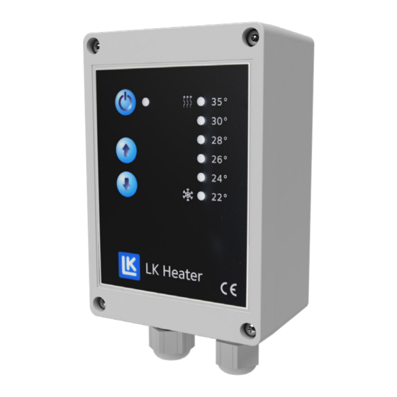
Function
On the controller the max water inflow tempera-
ture can be set up, from 22 ºC to 35 ºC.
The LK Heater can also be put in frost protection
mode with an adjustable water temperature to 10 ºC.
Key down the temperature setting to 22 ºC, and
press one more time so that the light for 22 ºC flashes
indicating frost mode, 10 ºC water temperature.
Installation
Note! LK Heater 350 should only be moun-
.
2
ted together with the LK Minishunt M60n.
The control unit is mounted in direct proximity to
the Minishunt installation. Fix the electrical cables
to the heater plus other cables in the near surroun-
ding to ensure that no cables can come in contact
with the housing of the heater brass tube. Mount
the supplied safety valve in the Minishunt outlet
according to the image below. The safety valve is
fitted with a self-sealing O-ring. The safety valve
also has a so called metallic seal which can make
it seem as if the valve is "slow" to install.
Ensure that the inflow sensor is located in the
brass tube's well pockets. The sensor should be
clamped with the clamping screw.
Note! The inflow sensor should always be
installed and connected during operation.
Assembly instructions | LK Heater 350
EN.33.C.77.2002
1 (3)
Advertisement

Summary of Contents for LK Systems LK Heater 350
- Page 1 ”slow” to install. The image shows the components to LK Heater 350 for two heating circuits. In the image LK Heater is assembled to LK Minishunt M60n which is shaded in the picture.
- Page 2 Installation of more than two heating circuits In cases where more than two heating circuits are to be connected, the LK Heater 350 can be screwed to- gether with the LK Mini Manifold. Note, however, that the maximum floor heating surface for the LK Heater is 12 m .
- Page 3 Assembly instructions | LK Heater 350 Dimensions LK Heater for a single floor heating circuit assembled with LK Minshunt M60n. EN.33.C.77.2002 LK Systems AB, Box 66, 161 26 Bromma, Sweden | www.lksystems.se 3 (3)