Table of Contents
Advertisement
Quick Links
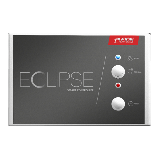
CONTROL UNIT
INSTALLATION AND OPERATING MANUAL
P
P
l
l
e
e
i
i
o
o
n
n
s
s
.
.
r
r
.
.
l
l
.
.
V
V
i
i
a
a
V
V
e
e
n
n
e
e
z
z
i
i
a
a
,
,
1
1
1
1
-
-
3
3
7
7
0
0
5
5
3
3
C
C
e
e
r
r
e
e
a
a
-
-
V
V
e
e
r
r
o
o
n
n
a
a
-
-
I
I
t
t
a
a
FOR MOTORS 24 Vdc OF
l
l
y
y
-
-
T
T
e
e
l
l
.
.
+
+
3
3
9
9
0
0
4
4
4
4
2
2
3
3
2
2
0
0
2
2
9
9
5
5
-
-
F
F
a
a
x
x
+
+
3
3
9
9
0
0
4
4
4
4
2
2
3
3
2
2
7
7
7
7
4
4
2
2
-
-
w
w
w
w
w
w
.
.
p
p
l
l
e
e
i
i
o
o
n
n
.
.
i
i
t
t
-
-
i
i
n
n
f
f
o
o
@
@
p
p
l
l
e
e
i
i
o
o
n
n
.
.
i
i
t
t
ECLIPSE SYSTEM
Version 1.2 of 24/06/2015
E N G L I S H
Page 1
Advertisement
Table of Contents

Summary of Contents for Pleion EOLIPSE
- Page 1 CONTROL UNIT ECLIPSE SYSTEM FOR MOTORS 24 Vdc OF INSTALLATION AND OPERATING MANUAL E N G L I S H Version 1.2 of 24/06/2015 Page 1...
-
Page 2: Table Of Contents
INDICE 1. Safety instructions ……………………....................3 2. Manufacture and regulatory references ..................4 2.1. Technical data ....................... 4 Plate and marking data 2.2.......................... 5 Supplied accessories 2.3.......................... 5 Overall dimensions for installation 2.4. ………………………………................5 3. Description ............................6 4. -
Page 3: Safety Instructions
1. INSTRUCTIONS FOR SAFETY ATTENTION: PLEASE CAREFULLY READ THE FOLLOWING SAFETY INSTRUCTIONS BEFORE STARTING THE INSTALLATION OF THIS APPLIANCE; THESE DATA ARE USEFUL TO PREVENT ELECTRICAL CONTACTS, INJURIES AND OTHER ISSUES. KEEP THIS MANUAL FOR FURTHER ADVICE. This control unit is only for the activation of solar collectors motors ECLIPSE. The use for different applications is not authorised by the manufacturer. -
Page 4: Manufacture And Regulatory References
2. MANUFACTURE AND REGULATORY REFERENCES • Control unit has been designed and made only for controlling and activating ECLIPSE system motors; any other use is forbidden. • Electrical wiring must meet the EU standards on electrical systems. • Control units are made in accordance with European directives and are certified with the mark. -
Page 5: Plate And Marking Data
2.2 PLATE AND MARKING DATA Each control unit is marked and can be put on the market and in use within European Union without further formalities. The mark on the product indicates, “presumption of conformity with the directives” issued by the European Community. The manufacturer has technical archive containing all documentation showing that all products have been tested and verified for approval in compliance with the directives. -
Page 6: Description
3. DESCRIPTION Control unit has been developed to activate ECLIPSE solar collector motors. Each unit can activate from 1 min. up to 4 max. motors. Operation of motors is sequential, not simultaneous. Control unit for ECLIPSE system Solar control unit STECA (mod. -
Page 7: Instructions For Assembly And Starting
4. INSTRUCTIONS FOR ASSEMBLY AND STARTING THESE INSTRUCTIONS ARE ADDRESSED TO QUALIFIED TECHNICAL PERSONNEL. In order to facilitate the installation operations and ensure the proper system functioning, it is recommended to follow those instructions and cautions. 4.1 SETUP AND WIRING 1. -
Page 8: Reset And First Turn On
8. Complete the electrical wiring path and make the proper electrical connections by following the wiring diagram on page 13. To facilitate the electrical connections gently remove the electrical junction boxes and then replace them properly. 4.2 RESET AND FIRST TURN ON The control unit is able to operate properly only if at the time of first turn on all the plastic layers are on the back of the solar collector. -
Page 9: Programming
4.3 PROGRAMMING The control unit is equipped with a protection system that allows to exclude the motors with anomalies. For the correct operation it is necessary to enable the motors connected to the control unit, switching the microswitches (SW1), depending on the number of motors connected, as shown in the chart below. PLEASE NOTE: The programming of the control unit can be performed only when it is not powered (Schuko disconnected). -
Page 10: Supplementary Connections
4.5 SUPPLEMENTARY CONNECTIONS 1. Connection in series of multiple control units For connection in series of multiple control units, it is necessary to connect terminals of the upstream control unit to terminals of the downstream control unit (see diagram below). In this way, the over temperature input signal is replicated on each cascade control unit, by using a single solar control unit. - Page 11 If there are multiple control units in series, the alarm remote signal can be implemented as follows: • dedicated signal for each control unit; • single signal for all control units. Page 11...
-
Page 12: Functioning
5. FUNCTIONING THIS CHAPTER DESCRIBES TWO DIFFERENT FUNCTIONING MODES OF THE CONTROL UNIT AND THEIR PROCESSING. ATTENTION. CONTROL UNIT HAS ALREADY BEEN FACTORY PROGRAMMED; SETTINGS CANNOT BE MODIFIED BY USERS, NOR BY PLEION TECHNICAL ASSISTANCE SERVICE. KEY/LED FUNCTION NUMBER AUTOMATIC mode BLUE led how to shift from AUTOMATIC –... -
Page 13: Automatic Mode
5.1 AUTOMATIC MODE Once voltage is given, control unit goes into AUTOMATIC mode (light BLUE led [1] on). In AUTOMATIC mode, control unit automatically manages the functioning of motors, that is the opening and closing of the dimming layers of ECLIPSE solar collector. Layers are kept under collector tubes, by allowing solar radiation of collector itself until an overtemperature signal acts (danger for stagnation) coming from the solar control unit. -
Page 14: Anomalies Alarm
5.3 ANOMALIES ALARM All motors supplied by Pleion have encoders, a device for detecting any malfunction and protect the functioning of motors. Control unit is then able to recognise the proper functioning of motors. In the event that there are some anomalies (for ex., a malfunctioning of motor due to an object stuck between plastic layers), control unit: interrupts the power supply to the motor with anomalies;... -
Page 15: Wiring Diagram At 1 - 4 Motors
6. WIRING DIAGRAM AT 1 - 4 MOTORS Page 15... -
Page 16: Declaration Of Conformity To Eu Directives
7. DECLARATION OF CONFORMITY TO EU DIRECTIVES S.G. Elettronica s.r.l. - Via Ferrari, 28 30037 Scorzè Venezia – ITALY P.IVA 02272310273 Tel. 041.5841973 / Fax 041.5841979 www.almot.it – info@almot.it The company S.G. Elettronica s.r.l. declares that the items are in conformity with all technical regulations related to products within the scope of application of the Community Directives 2006/95/CE, 2004/108/CE and 99/5/CEE, that is:... -
Page 17: Environment Protection
Legal warranty covers the product and each single part for a period of 24 months from the purchase date. Conventional warranty is an additional coverage given free of charge by the manufacturer. Its terms, effective date and duration are established by the “Certificate of Conventional Warranty” Pleion, and released as the product is made functioning. - Page 18 Pleion Srl Via Venezia, 11 - 37053 Cerea Verona - Italy Tel. +39 0442.320.295 - Fax +39 0442.327.742 info@pleion.it - www.pleion.it Pleion reserves right make modifications regarding technical, aesthetic and commercial details without any prior notice. V e r s i o n...
Need help?
Do you have a question about the EOLIPSE and is the answer not in the manual?
Questions and answers