Table of Contents
Advertisement
Quick Links
Power Supply for LED Illumination
VLP-2430-4 / 2460-4
Operation Manual
Thank you for purchasing a VAL product.
To use this LED power supply with optimum performance and safety,
please read this manual thoroughly before starting operation.
Keep this manual for the whole product lifetime.
The following warning symbols are used in this manual.
Be sure to fully understand the contents.
WARNING
A warning denotes a hazard that can cause severe injury or death.
CAUTION
A caution denotes a hazard that can cause injury or damage of equipment.
Rev. 1.1
Advertisement
Table of Contents

Summary of Contents for VAL VLP-2430-4
- Page 1 Power Supply for LED Illumination VLP-2430-4 / 2460-4 Operation Manual Thank you for purchasing a VAL product. To use this LED power supply with optimum performance and safety, please read this manual thoroughly before starting operation. Keep this manual for the whole product lifetime.
-
Page 2: Safety Regulations
5. Dispose the product conforming to the law in the region where the product is used. 2.General Description VLP-2430-4 and VLP-2460-4 are a power supply for VAL series or LED lighting unit made by VS Technology (Thailand) Co., Ltd. It can be used with input voltage range with AC100 ~240V and output wattage maximum totally 30W(2430-4) or 60W(2460-4) with 1CH and 2CH and 3CH and 4CH. -
Page 3: Confirming Package Contents
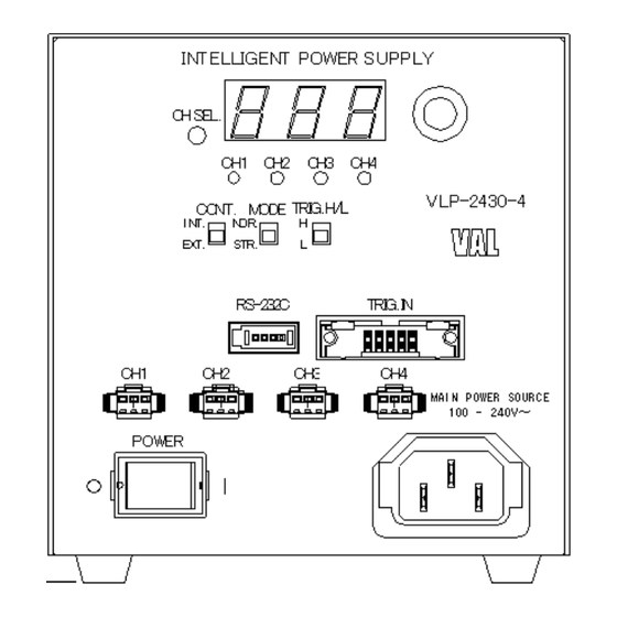
Ferrite core clamp filter for AC power cord *Applicable cable outer diameter 6 to 9mm. *Attach to AC power cord within 100mm from unit. This operation manual 4.Specification Model VLP-2430-4 VLP-2460-4 Input Voltage AC 100 – 240V (rated) ±10% 50/60Hz Power Consumption AC100V/1A – AC240V/0.5A... - Page 4 Rev. 1.1 5.Dimensions and Functions ① Power switch Power on at “I” side ② Intensity Volume Knob For digital control ③ Digital Display Display the setting of the light intensity or the setting of the lighting mode. ④ Channel Selection Switch Selects CH1, CH2, CH3, CH4.
-
Page 5: Operation
Rev. 1.1 6.Operation (1) Connections Confirm the power switch is OFF (on “0” side). Connect the LED lighting unit to CH1 or CH2 or CH3 or CH4 output connector on front panel of the product. Connect 3P socket of the AC power cord to power supply inlet on front panel of the product and connect 3P plug of the AC power cord to outlet. - Page 6 Rev. 1.1 7.Control with External Signals Use output signal cable of 3m or shorter. Do not apply too high current and voltage. CAUTION Do not use external connector except SELV circuit with reinforced insulation or a circuit with double insulation. Connector Communications Specifications Communications protocol...
- Page 7 Setting the lighting mode to @00S0400B8CRLF @00O0050CRLF @00N0300B2CRLF Strobe Mode at 200μs for CH2 of the VLP-2430-4 that the ID set to 00. -To set ON/OFF Signal in ON/OFF mode Specify the ID and the channel, and set ON/OFF signal. Setting example...
- Page 8 Light Unit ON/OFF BROWN/WHITE control input CH4 5 to 9 No used COMMON+ Yellow/Black *External Trigger Signal Connection Example External Circuits VLP-2430-4 Control Unit Transistor (NPN) 7.5kΩ open collector Light Unit ON/OFF control input 22kΩ Transistor (NPN) 7.5kΩ open collector...
- Page 9 Rev. 1.1 *Setting Procedures With external trigger input connectors pins 1 to 4, select the channels (CH1 to CH2 to CH3 to CH4) where you want to input an external trigger, and input trigger. Trigger signals are input from the external trigger input connector in ON/OFF Mode and Strobe Mode in both Internal Mode or External Mode.
-
Page 10: Optional Accessories
Rev. 1.1 9.Optional Accessories *External Control Cable Model: VL-EXCB1-3 Connector: XN2A-1470 (Manufactured by OMRON) *External Trigger Input Cable Model: VL-EXCB2-3 Connector: XG4M-1030-T (Manufactured by OMRON) 10.Warranty ・Duration of warranty The duration of the product warranty shall be two years from the day of product delivery. ・Extent of warranty If a fault or defect attributable under normal use during the warranty period, VS Technology (Thailand) Co., Ltd.
Need help?
Do you have a question about the VLP-2430-4 and is the answer not in the manual?
Questions and answers