Table of Contents
Advertisement
Quick Links
Advertisement
Table of Contents

Related Manuals for GEPA ARG-24 Series

Summary of Contents for GEPA ARG-24 Series
- Page 1 GEPA ARG Series Battery Charger with Battery Group User Guide...
- Page 2 Compatibility (EMC) Directive 2014/30/EU. Consult us for recycling or disposal of the device and batteries according to WEEE directive. Manufacturer Contact Details GEPA Elektronik San. ve Tic. Ltd. Şti. Name: Address: Zubeyde Hanim Dist. Sebzebahceleri St. No:93/36 Iskitler 06070 Altindag / Ankara, Turkey Web Site: www.gepaelk.com/...
-
Page 3: Table Of Contents
Table of Contents 1. General ............................1 2. Functions ............................2 2.1. Rectification ..........................2 2.2. Battery Charging ........................2 2.3. Metering ............................ 3 2.4. Alarm and Annunciation ......................3 2.5. Supervising ..........................3 2.5.1. Temperature Supervision ....................3 2.5.2. Fan Fault Supervision ......................3 2.5.3. -
Page 4: General
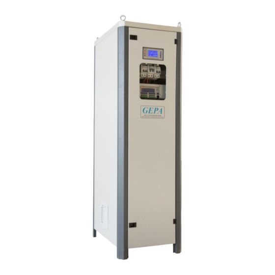
1. General ARG Series Battery Charger with Battery Group is specifically designed to be used in power stations and substations. The device combines battery charger and battery group in one cabinet; provides a compact solution for space constraint facilities. SCR based battery charger rectifies AC voltage and to supply DC supplied components and keep batteries charged. -
Page 5: Functions
2. Functions Simplified block schema of ARG Series Battery Charger with Battery Group is given at the below. ‘*’ marked functions are optional. 2.1. Rectification Microcontroller controlled 2-thyristor / 2-diode full bridge rectifier circuit and input isolation transformer is used for rectification. DC load and battery charging is controlled separately. -
Page 6: Metering
Default limits (0.1C and 0.3C) are determined for VRLA batteries. Refer to battery datasheet to verify maximum charge current limits. 2.3. Metering The device control unit measures following parameters • AC input voltage, • DC output voltage, • In-cabinet temperature. •... -
Page 7: Deep Discharge Protection
battery group doesn’t able to get charge or provide power. • If charger to battery group connection is faulty, broken cable or not properly connected multi-contact plug socket with models with drawers. 2.5.4. Deep Discharge Protection If AC input is not present and battery group voltage drops to preset deep discharge voltage level, this module disconnects battery group from load to prevent unrecoverable deep discharge state. -
Page 8: Surge Protective Devices
2.8. Surge Protective Devices Surge protective devices (SPD) are used as transient suppressers at AC input. SPDs will be installed before isolation transformer between L-PE and N-PE. This module is optional. Lightning protection shall be coordinated to make it effective; used SPDs are Class III according to IEC 61643-1 and not effective alone to protect devices in facility. - Page 9 The device has two cable entries, one on the side and one at the bottom of cabinet. Side entry which is next to MCBs and alarm module is easier to access. If bottom entry is preferred: o In models with drawers, there are no obstacles between terminals and entry or use cable spiral wrap as guide.
- Page 10 Wiring schemas are given at the below. MCB I varies according to input and output current. Schema 1: Power connections of 24V with multiple DC outputs Schema 2: Power connections of 110V and 24V Schema 3: Alarm module connections with RTU...
-
Page 11: Monitoring And Settings
3.2. Monitoring and Settings 3.2.1. Default Screen Default screen displays the following parameters: • In-cabinet temperature, • Mute symbol if buzzer is disabled, • Fan symbol if operating, • Time of day, • AC input voltage (V ), frequency (F •... -
Page 12: Editing Setting Parameters
3.2.3. Editing Setting Parameters This example describes how to edit ‘DC Output Voltage’ parameter; also applicable for editing other setting parameters. 1. On default screen press SET for Main Menu. 2. Press SET again to adjust any parameter on the screen. After pressing SET, cursor will be move onto ‘U’... -
Page 13: Setting Parameters
3.2.4. Setting Parameters DC Output Parameter Description Range Step Default 20.0 – 30.0 V for 24V Output voltage for floating 0.1 V for 24V 27.6 V 90 – 130 V for 110V charge. 1 V for 110V 124 V Output current limit for 1.0 –... - Page 14 Common Settings Parameter Description Range Step Default Active – Passive Buzzer Status of alarm buzzer. Active Control unit interface Türkçe - English Türkçe Language language. Deep 18 – 27 V for 24V Threshold of battery group 20 V for 24V Discharge 82 –...
-
Page 15: Technical Specifications
4. Technical Specifications 24V / 25A 110V / 25A (±%20) (±%20) Input Voltage 230 V or 120 V 230 V or 120 V 50 or 60 Hz (±%5) 50 or 60 Hz (±%5) Input Frequency Input Current 5.25 A 27 A Power Factor 0.82 0.66... - Page 16 GEPA GEPA Elektronik San. ve Tic. Ltd. Şti. Zubeyde Hanim Dist. Sebzebahceleri St. No:93/36 Iskitler 06070 Altindag / Ankara, Turkey Tel: +90 (312) – 341 – 4104 • Fax: +90 (312) – 384 – 0436 www.gepaelk.com • gepa@gepaelk.com Rev.4; 04/19...
Need help?
Do you have a question about the ARG-24 Series and is the answer not in the manual?
Questions and answers