
Summary of Contents for SANUPS D11A
- Page 1 M0008922 D11A Type R DC Input Small Capacity AC Power Supply 1kVA 100 V Model Instruction Manual...
-
Page 2: Table Of Contents
Introduction Thank you for choosing the SANUPS (D11A Type R). SAVE THESE INSTRUCTIONS This manual contains important instructions that should be followed during operation, installation, and maintenance of the DC-AC Inverter to protect the safety of the service technician* and the customers. To use the DC-AC Inverter correctly and safely, read this manual before using the DC-AC Inverter. - Page 3 Models This instruction manual is intended to be used for the following models. Check the model name of the DC-AC Inverter before use. Inverter Unit Model Name Parallel Operation Cabinet Model Name Number of Installable Bypass Circuit Units PD-D11AB03US D11A102B001US Unavailable PD-D11AB05US PD-D11AB06US...
-
Page 4: Safety Precautions
Safety Precautions § § PRECAUTIONS (IMPORTANT SAFETY INSTRUCTIONS) This Manual contains important instructions for operating and maintaining the DC-AC Inverter to protect the safety of the service technician and the customers. Before installing, operating, performing maintenance or inspecting the DC-AC Inverter, be sure to read this manual and accompanying documents carefully to obtain a clear understanding of the information related to its operation, safety and important precautions. - Page 5 Safety Precautions 1. Relocation and Transportation Precautions CAUTION ! Be careful to avoid falling or dropping the DC-AC Inverter during relocation or transportation, as bodily injury could result. Be careful to avoid back strain when handling the DC-AC Inverter. 2.
- Page 6 Safety Precautions 4. Operating Precautions WARNING ! Immediately shut the DC-AC Inverter off if it malfunctions, or if an unusual odor or noise is observed. Failure to do so may result in a fire. Do not open the cover of the DC-AC Inverter. There is danger of electric shock and equipment damage. PROHIBITED ...
-
Page 7: For Proper Operation
Operating Precautions § § § § (1) DC Input Power Supply The following table shows the DC input power supply for this DC-AC Inverter. Use the DC-AC Inverter according to its rated voltage. Cabinet Model Name Unit Model Name Rated Voltage Voltage Range PD-D11AB*3US D11A102B001US... -
Page 8: Installation Precautions
Operating Precautions § § (1) Installation must be in accordance with National Electric Code, Articles 110-16, 110-17 and 110-18. (2) This DC-AC Inverter is designed to permit the connection of the earthed conductor of the DC supply circuit to the earthing conductor at the equipment only use by restricted access locations. ※2 ※2 RESTRICTED ACCESS LOCATION shows a location for equipment where both of the following paragraphs apply. -
Page 9: Usage Precautions
Operating Precautions § § (1) Never short-circuit the output terminals or connect a load with a short-circuit current. Doing so will cause the protective functions to activate or the breaker to trip, preventing output. (2) Unsuitable load devices Do not connect laser printers, plain paper fax machines, copy machines, overhead projectors, vacuum cleaners, construction drills, or dryers as load devices. -
Page 10: Checking The Contents Of The Package
Operating Precautions § § After you open the package, check to make sure that it contains all of the following items. Does it contain the DC-AC Inverter and all accessories? Is the exterior of the DC-AC Inverter damaged or unusual? ... - Page 11 Part Names Blank page...
-
Page 12: External Dimensions And Part Names
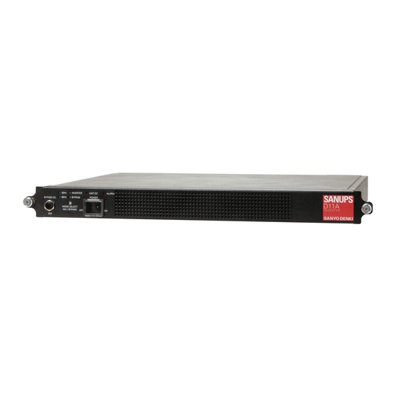
Operating Precautions § § § § Unit: mm [inch] Weight: Approx. 8 kg (17.6 lbs) D11A102B001US Front 480±3 [18.90±0.12] 465±3 [18.31±0.12] ③ ① ④ ② Back ⑥ ③ ⑩ ⑦ ⑤ Left side (21) 340.6 [13.41] (40) (40) [0.83] [1.57] [1.57] ⑩... - Page 13 Part Names Name Label Function POWER Switch for starting and stopping the unit (with a switch cover) ① Start/Stop Switch ON/OFF INVERTER Lit (blue) during output by inverter power supply ※ BYPASS Lit (yellow) during output by bypass power supply ②...
-
Page 14: Parallel Operation Cabinet
Operating Precautions § § Parallel operation cabinet for 3 units: PD-D11AB*3US Unit: mm [inch] ⑧ ⑪ ⑩ Weight: Approx. 10 kg (22.1 lbs) (Inside cover) ⑦ ⑨ Front PARALLEL PARALLEL STANDBY ⑥ ⑫ ・EIA standard compliant ・The figure shows the PD-D11AB13US model. ⑬... - Page 15 Part Names Parallel operation cabinet for 6 units: PD-D11AB*6US ⑧ ⑩ ⑪ ⑨ (Inside cover) ⑦ Front Unit: mm [inch] Weight: Approx. 13 kg (28.7 lbs) ⑥ ⑫ ・EIA standard compliant ⑬ ・The figure shows the PD-D11AB16US model. ⑭ ⑮ Left side ④...
-
Page 16: Transfer Signal Terminal Block
Operating Precautions § § ⑨ (100A/5V) Unit status signals ⑧ ⑦ COM (Common Signal Ground “G”) ⑥ ALRM (Failure/error) ⑤ AC OUT (Output) ④ DC IN-ALM (DC input error) OVERLOAD (Overload) ③ ② ① Signal Name Label Connection Definition When the DC-AC Inverter supplies AC output power from the bypass power supply, BYPASS OUT and ①... -
Page 17: Alarm Test/Operation Selector
Part Names § § 4 5 6 7 8 9 ⑤ ③ ④ ① ② Signal Name Label Definition Switch for alarm testing of units 1 to 6 failure Setting the switch to ON sends the alarm signal in a pseudo ①... -
Page 18: Installing A Cabinet
Installing a Cabinet § § When installing a cabinet and units, carefully follow the instructions in this instruction manual. Improper installation may result in electric shock, bodily injury, and/or fire. In accordance with the instruction manual, install the cabinet on a stable surface capable of bearing the weight (approximately 8 kg (17.6 lbs) for one unit, approximately 10 kg (22.1 lbs) for a parallel operation cabinet for 3 units, approximately 12 kg (26.5 lbs) for a parallel operation cabinet for 5 units, and... -
Page 19: Transportation And Installation
Installing a Cabinet § § In accordance with this instruction manual, install the cabinet on a stable surface capable of bearing the weight (approximately 8 kg (17.6 lbs) for one unit, approximately 10 kg (22.1 lbs) for a parallel operation cabinet for 3 units, approximately 12 kg (26.5 lbs) for a parallel operation cabinet for 5 units, and approximately 13 kg (28.7 lbs) for a parallel operation cabinet for 6 units) that is flat so that !... -
Page 20: Cabinet Wiring
Wiring § § § § Wiring should be performed only by a service technician. Incorrect wiring may result in electric shock and/or fire. A readily accessible disconnect device shall be incorporated external to the equipment. Make sure that the polarity is correct when wiring the DC input terminal block. Failure to do so may cause damage to the DC-AC Inverter. - Page 21 Wiring Acceptable wire table for DC input. Connectable Cable AWG (mm ) by ratings temperature of conductor Number of Connected Connector Tool for Terminal 60℃ (104°F) 75℃ (167°F) 90℃ (104°F) Units Min. Max. Min. Max. Min. Max. YA-5 (AD-955), AWG 1 AWG 1 AWG 1 AWG 4...
- Page 22 Wiring Aeceptable wire table for AC input. (These Terminal Blocks are only available for the PD-D11AB13US, PD-D11AB15US and PD-D11AB16US.) Exposed cable Screwdriver Connectable Cable AWG (mm ) by ratings temperature of conductor Number of length blade size Connected 60℃ (104°F) 75℃...
-
Page 23: Wiring The Transfer Signal Terminal Block
Wiring § § Wiring should be performed only by a service technician. ! Incorrect wiring may result in electric shock and/or fire. Make sure that the connections to the terminal block are not loose. Failure to do so may result in a failure or cause electric shock. CAUTION Use the following cables and tool to wire the transfer signal terminal block. -
Page 24: Procedure Until Dc-Ac Inverter Operation
Procedure Until DC-AC Inverter Operation § § The procedure until turning on the DC-AC Inverter is as follows. Be sure to perform the work in accordance with the procedure. Check the units ⇒ Page 22 Affix the unit number labels ⇒... -
Page 25: Preparations Before Installing Units
Preparations Before Installing Units § § § § Check the following items. Item Description Place Check Mark Is the exterior of the unit in any way damaged or □ Appearance deformed? □ Start/Stop Switch POWER Check that the POWER is OFF position. §... -
Page 26: Checking The Dip Switch
Preparations Before Installing Units § § Check the DIP switch settings of the unit, and if they are not compatible with your utility power source, change the settings with ON/OFF of the DIP switch. Check (Current settings) Item Description Unit 1 / 2/ 3 / 4/ 5 / 6 : Default) ★... -
Page 27: Installing Units
Installing Units § § The section describes how to install units in a cabinet mounted in a 19-inch rack. The following shows an example of installing units in a 6-unit cabinet. ① Insert Unit 1 under the display unit of the cabinet. Insert the unit straight all the way in until the connector on the back panel of the unit is securely inserted into the connector of the cabinet. - Page 28 Installing Units ⑥ When you install the sixth unit, remove blank panel B. ⑦ Insert the unit into the place from which you removed the blank panel, and tighten the left and right thumbscrews to fix the unit to the cabinet. Example of Installing Six Units ⑥...
-
Page 29: Preparations Before Operation
Preparations Before Operation § § § § When you select the operation mode on the LCD, the overload warning level is set. When you select the redundant operation (N + 1 unit) or increased capacity operation (N units) mode, the load capacity is calculated according to the number of units to operate and the operation mode. -
Page 30: Operating Procedures
Operating Procedures § § Note § § After the DC-AC Inverter is installed, be sure to check the start and stop operations. Note on before operating See §2.2 (4) “Installation Precautions.” when you perform a Start Procedure test using a fuse for the DC input before operating. Follow the procedure below to start the DC-AC Inverter. -
Page 31: D11A102B011Us Operating Procedures
Operating Procedures Note § § After installation, be sure to check the start and stop operations. Note on before operating ・ See §2.2 (4) “Installation Precautions.” when you perform a test using Start Procedure a fuse for the DC input before operating. ・... -
Page 32: Operation And Protective Functions
Operation and Protective Functions § § § § (1) Normal operation During normal operation, the DC input power is received and the AC power converted by the inverter is supplied to the load device. Unit 1 LED display The frequency display LED is set to 60 Hz in INVERTER the example. - Page 33 Operation and Protective Functions (3) When one unit fails When one unit fails, the ALARM LED (red) of the failed unit turns on. The remaining normal units continue to supply power to the load device. However, if one unit fails and the remaining normal units become overloaded, the normal units will be run in the same manner as when overloaded as described in (2).
-
Page 34: D11A102B011Us Basic Operation
Operation and Protective Functions § § (1) Normal operation During normal operation, the DC input power is received and the AC power converted by the inverter is supplied to the load device. LED display AC input Unit 1 The frequency display LED is set to 60 Hz in BYPASS the example. - Page 35 Operation and Protective Functions (3) When overloaded When the load current exceeds the overload warning level set on the LCD of the display unit during inverter power supply, the OVERLOAD LED (red) on the display unit turns on, and all the units automatically switch to bypass power supply.
-
Page 36: D11A102B011Us Special Function Operation
Operation and Protective Functions § § (1) Normal operation LED display Units installed in the upper part of the cabinet (parallel units 1 to 3) receive DC input power, and perform parallel operation while supplying AC power converted by the The frequency display LED is set inverter to the load device. -
Page 37: Protective Function Table
§ § ○: indicates that the LED turns on and transfer signal is (1) In the case of the D11A102B001US unit model and the PD-D11AB03US, 05US, and 06US cabinet models, functions including the protective ones shown in the following table are available for each inverter unit and cabinet. Inverter Unit Cabinet Cabinet... - Page 38 ○: indicates that the LED turns on and transfer signal is (2) In the case of the D11A102B011US unit model and the PD-D11AB13US, 15US, and 16US cabinet models, functions including the protective ones shown in the following table are available for each inverter unit and cabinet. Item Inverter Unit Cabinet...
-
Page 39: Inspection And Maintenance
Inspection and Maintenance § § . . Inspection and maintenance of the inside of the DC-AC Inverter should be performed only by a service technician. ! Electric shock, bodily injury, burn, smoke, or fire may otherwise result. Inspection should be performed after shutting down the DC-AC Inverter completely and CAUTION turning off the distribution board breakers for the DC and AC power supplies. -
Page 40: Maintenance By Service Technician
Inspection and Maintenance § § The user must not perform the maintenance described in this section. Be sure to contact your service technician for maintenance. Internal maintenance and inspection should be performed only by a service technician. Electric shock, bodily injury, burn, smoke or fire may otherwise result. ... -
Page 41: Procedure To Remove The Unit
Inspection and Maintenance § § Step ① Check□ Current value: Check the output current of the DC-AC Inverter. If the current value is larger than the rated current of the units not to be removed, reduce the load. Open the switch cover and turn the POWER switch OFF. -
Page 42: Procedure To Install The Unit
Inspection and Maintenance § § Note Even if you change the DIP switch settings after you start the unit, the changes will not become effective. Check the settings before you insert the unit into the cabinet. Step ① Check□ Check that the DIP switch settings of the unit to be installed are identical to those of the units that are already installed and operative. -
Page 43: Procedure To Install An Additional Unit
Inspection and Maintenance § § If you schedule the number of inverter units to be increased later, the breaker (UL489 approval) of the capacity in which the number of inverter units is ! increased. If the capacity of the breaker is insufficient after the number of inverter units is CAUTION increased, change the breaker (UL489 approval). -
Page 44: Procedure To Replace The Display Unit
Inspection and Maintenance § § Replacement should be performed only by a service technician. ! Electric shock, bodily injury, burn, smoke, or fire may result otherwise. The display unit should be replaced in accordance with the instructions in the instruction CAUTION manual. - Page 45 Inspection and Maintenance Remove the short piece “JP1.” Note JP1 Be careful not to lose the short piece “JP1” after you remove it. Be careful not to drop or lose it. Step ⑤ Check□ Remove the short piece JP1 of the new display unit. After removing the JP1, insert the display unit about halfway into the cabinet.
-
Page 46: Resetting The Bypass Breaker
Inspection and Maintenance § § Resetting of the bypass breaker should be performed only by a service technician. ! Failure to do so may result in an electric shock. Be sure to reset the bypass breaker after all units are shut down. CAUTION Failure to do so may result in an electric shock. -
Page 47: Procedure To Remove The Cabinet
Inspection and Maintenance § § Step ① Check□ Turn the load device OFF. Step ② Check□ Open the cover for the Start/Stop switch POWER on the front panel of the all units and turn the switch OFF. Open the switch cover After you operate the switch, close the cover. - Page 48 Inspection and Maintenance Blank page...
-
Page 49: Wiring And Settings For Parallel And Standby Operation
Wiring and Settings for Parallel and Standby Operation § § Wiring work should be performed only by a qualified service technician. ! Incorrect wiring may result in electric shock and/or fire. Make sure that the connections to the terminal block are not loose. Failure to do so may result in a failure or cause electric shock. -
Page 50: Lcd Display And Operation
LCD Display and Operation § § § § ② ④ ① ③ Name Label Function Sets the status display, total output voltage and current, and ① LCD Display - overload warning level of the unit UP key Goes up to the next set value ②... -
Page 51: Operating The Lcd
LCD Display and Operation § § Four minutes of inactivity causes the LCD screen display to disappear. Press any of the 3 keys to display the screen that disappeared. Follow the procedure below to operate the display select button. ① Press any one of the 3 keys to display the screen. ②... -
Page 52: Specifications
Specifications § § (1) Unit Item Standard or Performance Notes Model Name D11A102B001US D11A102B011US Output Capacity 1 kVA/1 kW Apparent power and active power Cooling System Forced air cooling Rated Voltage –48 V Variation Range –40.5 V to –57 V Max. -
Page 53: Warranty
Warranty § § Warranty for use: 1 year The product is warranted for the specified periods against electrical failures due to materials or workmanship. Free repair or replacement by a product with equivalent functions will be made when it is determined that failure has occurred because of defects in materials or workmanship.
Need help?
Do you have a question about the D11A and is the answer not in the manual?
Questions and answers