Table of Contents
Advertisement
Quick Links
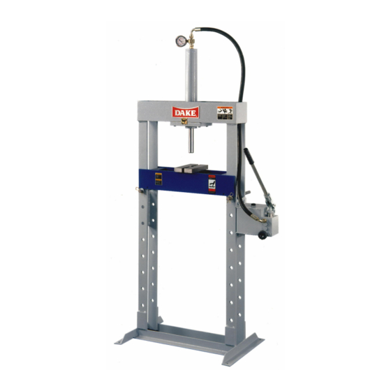
FORCE 10 & FORCE 20
Use and Maintenance Manual
Hydraulic Press-Manual Pump
Model No: _________________
Serial No: _________________
Force 10M /Force 20M1
724 Robbins Road
Grand Haven, Michigan 49417
616-842-7110
616-842-0859
Web:
E-mail :
Dura Press Models
Phone 800-937-3253
Fax 800-846-3253
www.dakecorp.com
customerservice@dakecorp.com
technicalsupport@dakecorp.com
1
06/10
Advertisement
Table of Contents

Subscribe to Our Youtube Channel
Summary of Contents for Dake Dura Press FORCE 10
- Page 1 724 Robbins Road Grand Haven, Michigan 49417 616-842-7110 Phone 800-937-3253 616-842-0859 Fax 800-846-3253 Web: www.dakecorp.com E-mail : customerservice@dakecorp.com technicalsupport@dakecorp.com Dura Press Models FORCE 10 & FORCE 20 Use and Maintenance Manual Hydraulic Press-Manual Pump Model No: _________________ Serial No: _________________ 06/10 Force 10M /Force 20M1...
- Page 2 Section I INTRODUCTION 1. This manual has been created by DAKE to give the Customer all the necessary information for regular use and correct maintenance of the hydraulic presses in the DURA PRESS series. It contains the use and maintenance instructions as well as the safety and calibrating instructions requiring your direct action.
- Page 3 Section II LIST OF SAFETY CHECKS ALWAYS ACT WITH CAUTION ATTENTION PRECAUTION Read the rest of this section very carefully before proceeding to read the following sections. CAUTION general When working always pay attention and be alert. Be careful. Be aware of possible hazards.
- Page 4 CAUTION pressure pipes The flexible or metal pipes of a system may hold fluids under pressure even with the system switched off. Before dismantling them, check on the diagram whether the section could be under pressure. In any case, loosen the fittings slowly. CAUTION hydraulic oil Very fine jets of high-pressure hydraulic oil can penetrate the skin: do not use your fingers to detect any leaks of hydraulic oil, neither put your face close to them, but use a...
-
Page 5: Table Of Contents
Section III TABLE OF CONTENTS SECTION I INTRODUCTION SECTION II LIST OF SAFETY CHECKS SECTION III TABLE OF CONTENTS SECTION 1.0 GENERAL SAFETY INSTRUCTIONS General instructions and definitions Description Press identification Safety labels General safety instructions SECTION 2.0 TECHNICAL DATA SHEET Cylinder and spare parts section Manual pump and spare parts section SECTION 3.0... -
Page 6: General Instructions And Definitions
This handbook is an integral part of the product; IT MUST be carefully conserved for future reference. FOR ANY REQUEST FOR CLARIFICATION, ASK YOUR EMPLOYER OR THE DAKE TECHNICAL SERVICE, AVOIDING ANY PERSONAL INITIATIVE THAT COULD CAUSE VERY SERIOUS OR FATAL ACCIDENTS. Before using the machine, read the warranty carefully. -
Page 7: Press Identification
1.4 PRESS IDENTIFICATION The press is fitted with a rating plate fixed in a visible manner on the rear as shown in Fig. 01 below. Dake part number and serial number on front name plate shown in Fig. 03 Fig. 03A Part No. - Page 8 Label 84487 Label 300168 Label 84399 Label Placement View 81002 300168 84487 Label 607 84399 06/10 Force 10M /Force 20M8...
-
Page 9: General Safety Instructions
1.6 GENERAL SAFETY INSTRUCTIONS Use of the press is allowed exclusively for trained and authorized personnel. When you leave the machine, even if only for a moment, make sure it is not in the pressing phase, dangerous for you and for others. In the event of confusion or uncertainty in the manner of operation to be made, refer to the user’s manual or call qualified personnel to resolve your doubts. -
Page 10: Cylinder And Spare Parts Section
2.1 CYLINDER AND SPARE PARTS SECTION Model Force 10M & Force 20M Breakdown Part Number Item Description Force Force Gauge Bar 300357 300358 Gauge in tons 301723 301722 Hand Pump - Complete 300366 301485 Hydraulic Cylinder 300652 301343 Complete Piston Gasket 300796 301558 Spring... - Page 11 Model Force 10M & Force 20M Breakdown Hand Pump Assembly Part Number Item No Description Force 10M Force 20M Piston Pump 302367 302367 Handwheel 302368 302368 20:29 Valve 302369 302369 31-32-33 Valve 302370 302370 Filter Rod assembly 302373 302373 Spring 302372 302346 302371...
-
Page 12: Unpacking
UNPACKING If the machine is supplied wrapped in plastic sheet, any accessories, spare parts and expendables are packed in cardboard boxes and positioned on top of the worktable. To remove the packing, cut the plastic wrap, taking care not to damage the machine or cardboard box. -
Page 13: Handling, Transporting And Positioning
Section 4.0 4.0 HANDLING, TRANSPORT AND POSITIONING For handling the packed machine, as described above (see section 3.0), it is necessary to use special lifting equipment whose maximum lifting capacity must be no lower than the total weight of the press. THE TOTAL WEIGHT OF THE PRESS PLUS PACKING IS SHOWN ON THE ADHESIVE TABS PLACED ON THE PACKING AND ON THE ACCOMPANYING... -
Page 14: Positioning The Press
4.2 POSITIONING THE PRESS Simple precautions are necessary for correctly positioning the press. Always consider the safety aspect not only in relation to the work carried out with the press, but also to the dangers originated by the other machines in the workplace. Before positioning, check that The floor is suitable for positioning the press that is it has no holes or subsiding portions, and that its capacity is sufficient to sustain the... -
Page 15: Filling The Press With Oil
Section 5.0 5.0 COMMISSIONING AND STARTING This section describes the operations to be followed on commissioning along with some advice for starting the machine for the first time. 5.1 FILLING THE PRESS WITH OIL To fill the press, use exclusively the oils indicated in the table or ones of equivalent reliability. -
Page 16: Maximum Pressure Adjustment
The maximum work pressure of the press is adjusted by pressure regulator valve suitably set and sealed with lead. DAKE DECLINES ALL LIABILITY FOR DAMAGE TO THINGS AND/OR PERSONS CAUSED BY TAMPERING WITH THE PRESSURE CONTROL VALVE FITTED ON THE UNIT. -
Page 17: Safety Instructions
Section 6.0 6.0 SAFETY INSTRUCTIONS THE MANUFACTURER DECLINES ALL LIABILITY FOR DAMAGE TO THINGS OR PERSONS CAUSED BY NON- OBSERVANCE OF THE SAFETY INSTRUCTIONS GIVEN IN THIS MANUAL WHICH SUPPLEMENT THE CURRENT LEGAL REGULATIONS IN WORKPLACES. IT IS EXTREMELY IMPORTANT FOR THE OPERATOR TO UNDERSTAND ALL THE SAFETY INSTRUCTIONS LISTED BELOW IN ORDER TO PREVENT DAMAGE TO THEMSELVES, TO THINGS OR TO OTHERS. -
Page 18: Operation
Section 7.0 7.0 OPERATION Before starting any operations, make sure there are no other persons in the immediate vicinity of the machine. IT IS STRICTLY FORBIDDEN TO PASS UNDER THE WORK TABLE. 7.1 CONTROLS To make the press work you have to stroke the pump control lever. The feed speed of the cylinder and the pressure will depend on the driving speed of the pump control lever. -
Page 19: Maintenance
Section 8.0 8.0 MAINTENANCE AUTHORIZED AND TRAINED PERSONNEL MUST CARRY OUT ROUTINE MAINTENANCE OPERATIONS. ALL MAINTENANCE OR CLEANING OPERATIONS MUST BE DONE WITH THE MASTER SWITCH OFF. (IF EQUIPPED) SPECIAL MAINTENANCE OPERATIONS (REPAIRS) MUST BE CARRIED OUT BY THE MANUFACTURER’S PERSONNEL ON THE PREMISES OF THE MANUFACTURER OR BY SUITABLY TRAINED AND SPECIALIZED PERSONNEL UPON AUTHORIZATION BY THE MANUFACTURER. -
Page 20: Malfunctioning, Causes And Remedies
- Head gasket damaged or - Replace worn Cylinder will not press - Lack of pressure from - Recondition pump pump - Pressure control valve set - Set valve * Call Dake Technical Service 1-800-937-3253 06/10 Force 10M /Force 20M20... -
Page 21: Putting Out Of Service
Section 10.0 10.0 PUTTING OUT OF SERVICE In the case of putting away for a long period it is necessary to empty the unit of oil and protect it suitably so there is no dust, moisture, or other foreign bodies, exposed to the unit that can damage the parts of the unit. - Page 22 Gauge Conversion 10 ton Bore 60 mm = 2.362” 10 Ton 302 bar 4565 PSI 5 Ton 151 bar 2282 PSI 4 Ton 121 bar 1825 PSI 3 Ton 90 bar 1369 PSI 2 Ton 60 bar 913 PSI 1 Ton 30 bar 456 PSI Gauge Conversion 20 ton...
Need help?
Do you have a question about the Dura Press FORCE 10 and is the answer not in the manual?
Questions and answers