
Summary of Contents for GBD DCD300
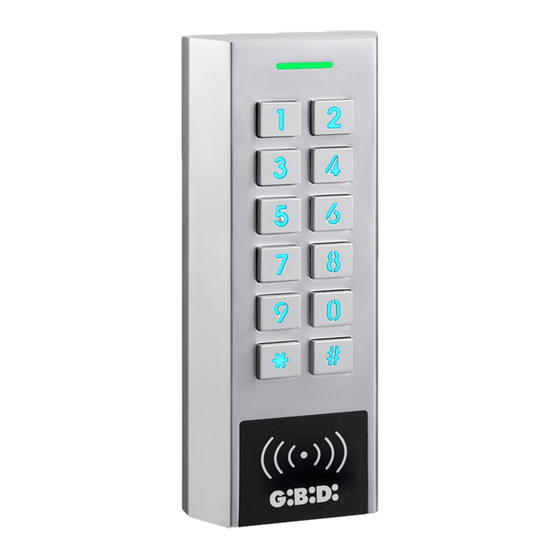
- Page 1 DCD300 DCD300 Waterproof multifunction keypad with double relay for stand-alone access control USER MANUAL...
-
Page 2: Technical Specifications
1 - TECHNICAL SPECIFICATIONS DCD300 Installation Wall mounting Material Metal alloy Programming By keypad Power supply 12/24V ac/dc Absorption at rest < 50mA Form of identification Code / Tag RFID or both Keypad 12 backlit metallic buttons 1-8 digits PIN lenght (up to 100.000.000 combinations) -
Page 3: Installation
3 - INSTALLATION Install the fixing support on a perfectly flat surface Fix the device on the fixing support from above, then pull down Tighten the device on the fixing support with the locking screw 4 - WIRING DESCRIPTION Wires Name Description Power supply 12-24V ac/dc... -
Page 4: Connection Diagram
5 - CONNECTION DIAGRAM 5.1 - Electric lock device - de-energised to release Electrical lock device - de-energised Diode (**) to release 1N4004 provided Power supply 12-24 V DC Push Button (PTE) (*) Clock (*) (*) Clock/Push Button (PTE): Enable relay for "timed relay" (see chap. - Page 5 5 - CONNECTION DIAGRAM 5.2 - Electric lock - energised to release Electric lock - energised Diode (**) to release 1N4004 supplied Power supply 12-24 V DC Push Button (PTE) (*) (*) Push Button (PTE): Enable relay for "timed relay" (see chap.
- Page 6 5 - CONNECTION DIAGRAM 5.3 - Device controlled by a dry contact NO Control from dry contact NO Transformer 12-24 V AC/DC Push Button (PTE) (*) (*) Push Button (PTE): Enable relay for "timed relay" (see chap. 10) or as long as the contact is closed.
- Page 7 5 - CONNECTION DIAGRAM 5.4 - Connection of a door switch to manage the alarm if door open too long and/or door forced (see chap. 10) Power supply 12-24 V DC Buzzer, siren, flash, relay,... This output uses only DC current Position contact...
-
Page 8: First Power Up
6 - FIRST POWER UP • At first power up, the blue LED and the Buzzer works for 3s, then the device switches into “Stand-by” with flashing blue LED. • The entry of the default PIN 8 8 8 8 8 8 ,then # enables the relay 1 for 5s (green LED fixed). - Page 9 8 - CHANGE OF DEFAULT MASTER CODE WARNING: Change the default Master Code at your first installation. Default Master code = 8 8 8 8 8 8 New Master code = ........ The device must be in Programming mode, see Chap. 7 Buttons LED / Audible beep 0 (enables the function)
- Page 10 Resume from point 1 to add another user Yellow LED Enter another function or press to exit from Programming mode Blue 9.2 - ADDITION OF CARD/TAG IN SUCCESSION The device must be in Programming mode, see Chap. 7 Buttons LED / Audible beep 1 2 (enables the function) Yellow LED Enter User ID of the 1st user...
- Page 11 OK = Green LED Read the Card/Tag or enter + 1 Beep the number of the Card/Tag, Error = Red LED then press # + 5 Beeps Resume from point 1 to add other user Yellow LED Enter another function or press to exit from Programming mode Blue 9.4 - USER /S CANCELLATION...
- Page 12 10 - ADVANCED FUNCTIONS 10.1 - RELAY 1 CONFIGURATION The device must be in Configuration mode, see Chap. 7 Buttons LED / Audible beep 3 1 (enables the function) Yellow LED OK = Green LED Timed relay (default adjustment + 2 Beeps nter the duration from at 5 sec.).
-
Page 13: Keypad Backlight
The device must be in ProgramminG mode, see Chap. 7 Buttons LED / Audible beep 4 (enables the function) Yellow LED Enabling of Doorbell button OK = Green LED + 1 Beep mode. Press 1 ,then # OK = Green LED Enter the duration from 1 to 300 s, + 2 Beeps press #... -
Page 14: Alarms Configuration
10.5 - BUZZER SOUND VOLUME Buzzer volume when you enter a code or read a Card/Tag. The device must be in Programming mode, see Chap. 7 Buttons LED / Audible beep 6 1 (enables the function) Yellow LED OK = Green LED Adjust the volume from 0 to 5 + 2 Beeps press # . - Page 15 OK = Green LED Alarm output : 1 = Enabled / + 2 Beepd 2 = Disabled (during the alarm) Error = 3 Beeps then press # OK = Green LED Disables open door detection + 2 Beeps (default adjustment) Press 2 then # Error = 3 Beeps Yellow LED...
- Page 16 11.3 - MAX.NUMBER OF WRONG ATTEMPTS ALARM After 10 wrong attempts of Card/Tag reading or wrong entering of PIN code, the keypad will block and any attempt will not be possible for 10 minutes. The Doorbell button mode will be enabled even if the alarm is working.
-
Page 17: Back To Factory Parameters
Buzzer: OK = Green LED + 1 Beep 1 = Enabled / 2 = Disabled (during the alarm) then press # Error = 3 Beeps OK = Green LED Alarm output : 1 = Enabled / + 2 Beeps 2 = Disabled (during the alarm) Error = 3 Beeps then press # OK =... -
Page 18: Declaration Of Conformity (Ce)
The manufacturer: GI.BI.DI. S.r.l. Via Abetone Brennero, 177/B, 46025 Poggio Rusco (MN) - ITALY declares that the product: MULTIFUNCTION KEYPAD DCD300 Code: AU02201 is in conformity with the following Directives: • 2014/53/UE • 2011/65/UE and that the following harmonised Standards have been applied: •...
Need help?
Do you have a question about the DCD300 and is the answer not in the manual?
Questions and answers