
Related Manuals for Photonic Universe MT11


Summary of Contents for Photonic Universe MT11
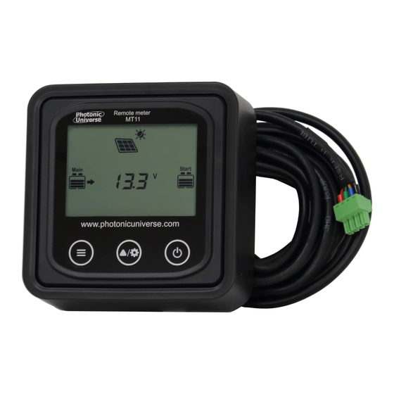
- Page 1 REMOTE METER Model: MT11 INSTRUCTION MANUAL For use with DM series dual battery MPPT solar charge controllers...
-
Page 3: Table Of Contents
Contents Important Safety Instructions ............1 2. Overview ................... 2 3. Product Components ................ 3 4. Installation ..................4 4.1 Mounting Frame (optional accessory, included) ......4 4.2 Wall installation steps ............... 5 4.3 Surface mounting steps ............7 5. Product Features ................8 5.1 Front View ................ -
Page 4: Important Safety Instructions
General safety information Please inspect the MT11 thoroughly after it is delivered. If there is any damage, document this with photos and contact the shipping company or seller for assistance. Please read this manual carefully before installing the product and ... -
Page 5: Overview
2. Overview The MT11 remote meter is an accessory which is compatible with the DuoRacer (DM series) MPPT solar controller. It can monitor the running data and working status of the controller, set the battery type and temperature units, and reset the generated energy counter. -
Page 6: Product Components
3. Product Components Remote meter MT11 5m communication cable (Model: CC-RS485-RS485-3.81-4P-500) Optional Mounting Frame ... -
Page 7: Installation
4. Installation 4.1 Mounting Frame (optional accessory, included) -
Page 8: Wall Installation Steps
Step 2: Use four PA4.2×32 self-tapping screws to fix the frame to the wall. Step 3: Remove the decorative shell. Step 4: Use four M4×8 pan head screws to mount the MT11 screen onto the frame. Step 5: Install the decorative shell over the screen. -
Page 10: Surface Mounting Steps
Step 3: Remove the decorative shell. Step 4: Use four M4×8 cross recessed pan head screws with M4 nuts to mount the MT11 screen onto the surface. Step 5: Install the decorative shell. NOTE: Consider the plugging/unplugging space and the length of... -
Page 11: Product Features
5. Product Features 5.1 Front View LCD display screen Remote meter operation interface. Refer to chapter 6 for details of display and operation. Buttons The meter buttons include two function buttons and one switch button. 1. PV array parameters Press the button 2. -
Page 12: Rear View
3. Browse the starter battery parameters automatically ( 1. Browse the PV array parameters 2. Browse the storage battery Press the button parameters 3. Browse the starter battery parameters Press the button Temperature units/Battery type and hold for 5s Press the button Turn the meter ON Press the button Turn the meter OFF... - Page 13 RS485 communication port Used to connect to the solar controller which, provides power and data to the MT11. Communication cable models CC-RS485-RS485-3.81-4P-500 (Included, 5m length) CC-RS485-RS485-3.81-4P-1000 (Optional, 10m length) CC-RS485-RS485-3.81-4P-2000 (Optional, 20m length) Pins definition Definition DC5V...
-
Page 14: Display And Operation
6. Display and Operation 6.1 LCD display Icon Instruction Icon Instruction BATT1 battery capacity BATT2 battery capacity level 0~12% level 0~12% ① ① BATT1 battery capacity BATT2 battery capacity level 13%~35% level 13%~35% ① ① BATT1 battery capacity BATT2 battery capacity level 36%~61% level... -
Page 15: Auto Global View Mode
① ① BATT1 battery capacity BATT2 battery capacity level level 87%~100% 87%~100% PV array Night BATT1 charging icon Display the parameters BATT2 charging icon of the PV array Display the parameters BATT1 temperature of BATT1 parameters Display the parameters AES signal icon of BATT2 Setting icon Battery type icon... - Page 16 Display Loop: PV voltage → PV current → PV power→ Battery power → BATT1 voltage → BATT1 current → Max. BATT1 voltage → Min.BATT1 voltage → BATT1 temperature → BATT1 battery type → BATT2 voltage → BATT2 current → Max. BATT1 voltage →...
-
Page 17: Temperature Units
6.3 Temperature units Operation: Step 1: Press the button under the battery temperature interface. Step 2: Press the button to select the temperature unit. Step 3: Press the button to set successfully. 6.4 Clear the generated energy Press the button and hold for 5s to clear the generated energy. -
Page 18: Battery Type
6.5 Battery type 1)Operation: Step 1: Press the button and hold for 5s under the battery type interface. Step 2: Press the button when the battery type interface is flashing. Step 3: Press the button to confirm the battery type. 2) Battery type BATT1 12V Sealed BATT1 24V Sealed... - Page 19 1) Lead-acid Battery Control Voltage Parameters The parameters below are for a 12V system at 25 ºC. Please double the values in a 24V system. Battery type Sealed Flooded User Voltage parameter Over Voltage Disconnect Voltage 16.0V 16.0V 16.0V 9~17V Charging Limit Voltage 15.0V 15.0V...
- Page 20 A. Over Voltage Disconnect Voltage > Charging Limit Voltage ≥ Equalize Charging Voltage ≥ Boost Charging Voltage ≥ Float Charging Voltage > Boost Reconnect Charging Voltage. B. Over Voltage Disconnect Voltage > Over Voltage Reconnect Voltage C. Low Voltage Reconnect Voltage > Low Voltage Disconnect Voltage ≥ Discharging Limit Voltage.
- Page 21 Under Volt. Warning Voltage 10.5V 9~17V 12.0V Low Volt. Disconnect Voltage 9.3V 9~17V 11.0V Discharging Limit Voltage 10.8V 9.3V 9~17V The following rules must be observed when modifying the parameter values in User battery type for a lithium battery. Over Voltage Disconnect Voltage > Over charging protection voltage (Protection Circuit Modules (BMS))+0.2V;...
-
Page 22: Fault Indication
6.6 Fault indication Fault Instruction BATT1 Battery level shows full, battery overvoltage frame blink, fault icon blink. BATT1 over- Battery level shows empty, battery discharged frame blink, fault icon blink. Battery level shows current capacity, battery frame blink, fault BATT1 over icon blink, the temperature icon temperature blink, the temperature value blink,... -
Page 23: Technical Specifications
7.Technical Specifications Compatible models DM series (DM1024/DM2024/DM3024) Self-consumption (Power on) 13mA/5Vdc Self-consumption (Power off) 4mA/5Vdc Communication protocol RS485 Communication port 3.81-4P RS485 cable CC-RS485-RS485-3.81-4P-500 (5m) Environmental temperature -20ºC~+70ºC Storage temperature range -20ºC~+70ºC Enclosure IP20 Screen unit dimensions 98.4×98.4mm Frame dimensions 114×114mm Weight 0.11kg... - Page 24 Photonic Universe Ltd Tel: + 44 (0) 20 3150 11 11 Fax: + 44 (0) 20 3150 12 12 E-mail:info@photonicuniverse.com Website: http://www.photonicuniverse.com...
Need help?
Do you have a question about the MT11 and is the answer not in the manual?
Questions and answers