Table of Contents
Advertisement
Advertisement
Table of Contents

Related Manuals for Malvern Instruments ZETASIZER


Summary of Contents for Malvern Instruments ZETASIZER
- Page 1 ZETASIZER NANOSAMPLER BASIC GUIDE MAN0497-01-EN-00 Issue date: 07 April 2014...
- Page 2 Malvern® and the green “hills” logo are registered trademarks in the UK and/or other countries, and is owned by Malvern Instruments Ltd. Zetasizer® is a registered trademark in the UK and /or other countries, and is owned by Malvern Instruments Ltd.
-
Page 3: Table Of Contents
Contents CONTENTS Introduction About this manual Access to the instrument Assumed information Where to get help Health & Safety General warnings and regulations Electrical warnings and regulations Power cords and power safety Sample handling warnings Storage and disposal Additional safety considerations Site requirements Environmental conditions System requirements... - Page 4 Contents Troubleshooting Appendix Specifications Regulatory statements...
-
Page 5: Introduction
INTRODUCTION This section covers the following information: About this manual Access to the instrument Assumed information Where to get help... -
Page 6: About This Manual
Set out various maintenance and troubleshooting procedures. Provide the specifications of the instrument. Product documentation structure This manual should be used in conjunction with the documentation for the Zetasizer Nano instrument. As a minimum all users of the NanoSampler must read the following documentation: Zetasizer Nano Basic Guide - the essentials required to get started, including health and safety. -
Page 7: Access To The Instrument
Introducti on Help system The Help system is Integrated with the Zetasizer software, and provides searchable, con- text-sensitive information covering all software features. Access to the instrument This manual refers to the various people who will have access to the instrument, as fol- lows. -
Page 8: Assumed Information
This section gives information on the various channels in place to get help with your Nan- oSampler system. Help desk All queries about the system should be directed to your local Malvern Instruments rep- resentative, quoting the following information: Model and serial number of the instrument (usually located on the outside cas- ing of the instrument). - Page 9 Introducti on Remote support Malvern Instruments offers a remote support service, delivered by an Internet connection. Benefits include fast and efficient fault diagnosis, reducing downtime and costs. Malvern website - www.malvern.com The Malvern Instruments website offers a comprehensive range of particle char-...
-
Page 11: Health & Safety
HEALTH & SAFETY This section provides detailed health and safety information applicable to the Nan- oSampler instrument. All users of the system must read this information. This section provides the following information: General warnings and regulations Electrical warnings and regulations Power cords and power safety Sample handling warnings Storage and disposal... -
Page 12: General Warnings And Regulations
The instrument must only be stored or operated in environmental conditions conforming to the specification in the Site requirements section. Warning! Use of the system in a manner not specified by Malvern Instruments Ltd. may impair the protection provided by the system. - Page 13 H ealth & Safety Power cord set requirements Power cord sets must meet the requirements of the country where the product is used. For further information on power cord set requirements, contact a Malvern Instruments representative. General requirements The requirements listed below are applicable to all countries: The power cord must be approved by an acceptable accredited agency responsible for evaluation in the country where the power cord set will be installed.
- Page 14 H ealth & Safety The power cord supplied is equipped with a grounding connection to ensure grounding integrity is maintained. Advice on use of extension leads Follow this advice when using single or multiple socket extension leads. These are also called trailing sockets.
-
Page 15: Sample Handling Warnings
H ealth & Safety Sample handling warnings Always handle all substances in accordance with the COSHH (Control Of Sub- stances Hazardous to Health) regulations (UK) or any local regulations concerning sample handling safety. Before using any substance, check the Material Safety Data Sheets for safe hand- ling information. -
Page 16: Storage And Disposal
Refer to local regulations on disposal of equipment; in Europe refer to the inform- ation below. Seek advice from the local Malvern Instruments representative for details. Decontaminate the instrument if hazardous materials have been used in it. The following is applicable in the European Union and other European countries with sep-... -
Page 17: Additional Safety Considerations
To maintain the specified performance of the system, maintenance must be carried out as indicated in this manual. Malvern Instruments offers service contracts and preventive maintenance services. Please contact your local dealer or the nearest sales office for more information. - Page 18 H ealth & Safety Use of open fire in the vicinity of this system must be strictly prohibited. Do not install the system in the same room with any other equipment that emits or could potentially emit sparks. Sample containers (vials) should be sealed to minimize any risks related to solvent vapor. Do not allow solvents to accumulate in the system.
-
Page 19: Site Requirements
SITE REQUIREMENTS Several criteria must be satisfied at the installation site to ensure the effective and safe functioning of the NanoSampler. This section provides detailed information on these requirements. The following topics are covered: Environmental conditions System requirements Installation... -
Page 20: Environmental Conditions
Avoid passing electrical cables through areas where liquids can be spilled. Warning! Do not position the system so that power sockets are obstructed. They may need to be disconnected during an emergency. System components weight Component Weight NanoSampler Approx. 19kg Zetasizer Nano (ZSP) 19kg Computer and Printer See manufacturer’s documentation... -
Page 21: System Requirements
S i te requi rements Operating environment Operating environment Indoor use only Operating altitude up to 2000m Operating temperature 10-40°C Operating humidity 20-80% RH Transport and storage requirements Store the unit in a dry place where no mold will form. Transport and storage temperature -25-60°C Transport and storage humidity max. - Page 22 Computer Monitor umentation Computer specification and usage Note: The NanoSampler requires the installation of Zetasizer 7.10 software or later. Contact the Malvern Helpdesk or website for the recommended computer specification; otherwise consult the Software Update Notification document supplied on the soft- ware CD.
-
Page 23: Installation
Move the instrument Upgrade the computer Moving the instrument If it is necessary to move the system, please contact Malvern Instruments for guidance. Warning! Removal of the covers by unauthorized personnel will invalidate the warranty of the instrument. Note: If the original setup was performed as part of an IQ/OQ, moving the sys- tem invalidates this. - Page 24 1. Remove the old version of the software using the Add/Remove Programs function in the Windows Control Panel. 2. Insert the new Zetasizer software CD into the CD drive. 3. If Autorun is enabled, the software will install automatically. (If it is not enabled,...
-
Page 25: Nanosampler Hardware
NANOSAMPLER HARDWARE This section provides information on the typical hardware setup of a NanoSampler and gives more detail on the connections available. The following topics are covered: System configuration Using the hardware... -
Page 26: System Configuration
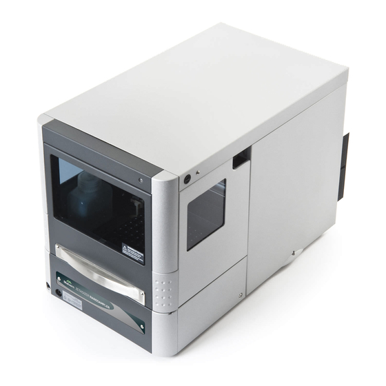
System configuration The NanoSampler is a versatile, compact sample delivery system that ensures highly pre- cise and reproducible automated loading of samples into your Zetasizer Nano. With com- pletely unattended operation the NanoSampler maximizes the productivity of your Zetasizer Nano and is ideally suited for laboratories where reproducibility and multivariate studies are important. - Page 27 NanoS ampler hardware Front panel (closed/open) 1. Front panel handle 2. Observation window 3. Drainage ports 1. Front panel (open position) 2. Tubing guide 3. Wash liquid bottle (external bottle required for 96 vials) 4. Vial adapters holding sample vials...
- Page 28 NanoSampler hardware Interior (front) The NanoSampler's sampling compartment houses the following parts: 1. Syringe 2. Needle arm 3. Injection valve 4. Valve leak bin 5. Sample compartment 6. Needle wash position / wash station 7. Wash liquid bottle...
- Page 29 NanoS ampler hardware Back panel The back panel of the instrument has the following items: 1. USB connector 2. Warning label 3. On/off switch 4. Fuse 5. Power connector...
-
Page 30: Using The Hardware
The system can be loaded with either one or two trays, each of which can contain any number of vials (up to 48) as required by your analysis. Caution: only use vial holder plates supplied by Malvern Instruments. This is due to varying pitches of plates from different manufacturers, which could res- ult in damage to the needle. - Page 31 NanoS ampler hardware 2. Then slide the door into the instrument. Note: before closing the front panel door withdraw the door fully by pulling it gently towards you.
- Page 32 NanoSampler hardware Removing the cover For easier access to the sampling area, remove the cover as described below: 1. Press the two black buttons on either side (top) of the NanoSampler sim- ultaneously: 2. Then gently pull the cover towards you.
- Page 33 NanoS ampler hardware Loading plates To load the plates ensure they are oriented as shown in the illustration and carefully insert into the NanoSampler being careful not to agitate the samples: 1. Tray 1 2. Tray 2 3. NanoSampler tray holder...
-
Page 35: Using The System
USING THE SYSTEM This section outlines the NanoSampler workflow and provides details on how to perform each step. The topics covered in this section include: Workflow overview System and sample preparation NanoSampler feature key Software configuration Vial position files... -
Page 36: Workflow Overview
Usi ng the system Workflow overview The flow-chart below details the process required to make a NanoSampler measurement. -
Page 37: System And Sample Preparation
1. Prepare samples using 1.5mL vials and load into the NanoSampler. 2. Check that the Zetasizer Nano is switched on and that the AutoSampler Features key is active in the Zetasizer software. - Page 38 Power cords and power safety on page 10 for more safety information. 3. Switch on the NanoSampler. 4. Start the Zetasizer software on your computer. Fluid connections 1. Connect the drain tubing to the waste outlet. 2. Fill the wash solvent bottle inside the sampling compartment of the NanoSampler with distilled water and propanol (80/20 v/v%) or mobile phase.
-
Page 39: Nanosampler Feature Key
Usi ng the system Filling vials Note: replacement vials are available to order from Malvern Instruments. Fill your sample vial, ensuring no air bubbles are present in the sample. A minimum sample volume of 750 μl is required for one analysis; 1.6 mL is required for three rep- licate analyses. -
Page 40: Software Configuration
See the Zetasizer User Manual for more details. For a NanoSampler measurement, ensure: The measurement type selected is Size. The cell specified is the Quartz Flow Cell, ZEN 0023. The process for creating SOPs is covered in detail in the Help system and the Zetasizer Nano User Manual. - Page 41 Usi ng the system Creating the SOP Playlist Through the SOP Player you can use the NanoSampler to : Run an SOP on an individual well. Run an SOP on a range of wells. To start the SOP player, choose: Measure-SOP Player From here you can build up a playlist of actions to direct the NanoSampler.
- Page 42 Usi ng the system Wash The wash step pumps transport fluid through the Quartz Flow Cell in order to remove sample. One wash cycle is equivalent to pumping 1000 µL through the Flow Cell. To add a wash step, left click on the Wash icon. The number of wash cycles in the wash step is shown under the Properties tab (3 by default).
- Page 43 Usi ng the system The following options are common to all running methods: Perform wash between vials/before or after sequence/between aliquots - the wash sequence flushes the flow cell and relevant tubing (the needle itself is washed after any sample load step and is not adjustable). The number of wash cycles will be as specified in the default settings unless manually edited.
- Page 44 Usi ng the system The position of the vial to be analyzed is identified by Tray, Row, and Column (the default starting position is Tray 1, Row A, Column 1). To edit these settings click the relevant prop- erty and enter the correct number/letter. To change the Sample Name click on the SOP icon and enter the correct title in the Prop- erties tab.
- Page 45 Usi ng the system 1. From the Naming and positioning section, select Single Vial. 2. Enter the Position of the vial using the Tray, Row and Column selection options. By default, the position is Tray 1, Row A, Column 1. 3.
- Page 46 Usi ng the system 1. From the Naming and positioning section, select Range. 2. Specify both the First position (where the sampling commences) and the Last pos- ition (where the sampling ends). Note: using this method, vials must be placed in the plate in sequence - it is not possible to sample from non-contiguous vials using this function - instead the Load from file option should be used.
- Page 47 Usi ng the system The software would be configured as shown: 3. Click OK to confirm the settings. 4. The system now prompts you to locate the SOP you want to use for this meas- urement (this must be a size SOP) - do this and click Open to confirm your selec- tion.
- Page 48 Usi ng the system Each individual aliquot is automatically assigned a unique identifier based on the Tray pos- ition and aliquot number. The playlist can be reviewed and edited if required. Missing vial action Click the cog icon on the Autosampler Actions bar to display the Autosampler settings window: The system can be set so that any wells that do not contain a vial are dealt with in a con- sistent way.
-
Page 49: Vial Position Files
Usi ng the system Whilst the measurements are taking place, it is possible to monitor the progress of the measurement on the SOP Player window using, for example the Multi-view, Intensity PSD or Log sheet tabs. Vial position files Normally you set a range of wells from which to sample, based on a defined start and end point and capturing all wells that fall into that range. - Page 50 Usi ng the system When the file has been created, save in the Text (Tab Delimited).txt format. Note: when viewing a vial position file in Excel the labeling in Excel of rows and columns must be ignored - columns are actually rows. For example, H1 in Excel is actually the vial position A8.
-
Page 51: Maintenance & Troubleshooting
MAINTENANCE & TROUBLESHOOTING The instrument is designed to minimize supervisor/operator maintenance. This topic explains the routine user maintenance procedures that can be performed. Warning! Unless advised within the content of this manual, only Malvern Instru- ments trained personnel are permitted to remove the main covers from the instru- ment or connected devices. -
Page 52: Maintenance
Tubing Note: a tubing spares kit is available to order from Malvern Instruments. The NanoSampler tubing covered in this section is user-replaceable. All other tubing must be assumed to be only replaceable by your Malvern service engineer - contact Malvern Instruments if in doubt. - Page 53 Undo the retaining connector from the top tube, where it connects to the right side of the valve at the top of the syringe. Remove the tube. Replacement is a reversal of the removal process. Note: ensure that only parts supplied by Malvern Instruments are used.
- Page 54 Mai ntenance & Troubleshooti ng Waste tubing The following connections for disposal of waste liquids are made: General waste: connect the drain tubing (in the installation kit of the Nan- oSampler) to the left-hand drain hose connector (see System configuration on ).
- Page 55 Mai ntenance & Troubleshooti ng Replacing fuses If you need to replace the fuses, ensure that you install fuses of the same type and rating. Fuses are located in the fusebox at the back of the NanoSampler (see System con- ).
- Page 56 Mai ntenance & Troubleshooti ng Troubleshooting The following table provides details on potential problems and how to resolve them: Problem Possible Cause Remedy Run full purge on system. Ensure Unexpected or "flat line" meas- Blocked tubing washes are built into the SOP playl- urements ist.
- Page 57 The following errors may occur with the NanoSampler. These are automatically generated by the system and written to the log file, which can be opened in any text editor: C:\Program Files (x86)\Malvern Instruments\Zetasizer Soft- ware\Autosampler.log Note: the errors listed here are those for which a remedy can be performed by the user.
- Page 58 Mai ntenance & Troubleshooti ng Syringe dispenser unit Error Code Description Action Syringe valve did not find destination pos- ERROR 324 Check belt and pulleys ition. ERROR 330 Syringe home sensor not reached. Check belt and pulleys ERROR 331 Syringe home sensor not de-activated. Check belt and pulleys ERROR 334 Syringe position is unknown.
- Page 59 APPENDIX This section contains the following information: Specifications Regulatory statements...
- Page 60 Dimensions 300 mm (w) x 510 mm (d) x 360 mm (h) Weight 19 kg Note: For physical dimensions of the Zetasizer Nano, please refer to the Zetas- izer Nano Basic Guide. Electrical Power requirements 95 - 240 Vac +/-10%, 50-60Hz...
- Page 61 Appendi x Sample capacity 2 racks of 48 1.5mL vials Maximum viscosity 6.44cP dimensions (incl. cap) Max. plate/vial height: 47 mm (incl. Vial/Plate septa or cap) Loop volume (sample / buffer) 1000µL Vial detection Missing vial/well plate detection by sensor Switching time injection valve Electrically <...
- Page 62 Appendi x Regulatory statements FCC Notice (US only) The Federal Communications Commission (FCC) mark on this product signifies con- formance to FCC regulations relating to Radio Frequency Devices. These have been sat- isfied by testing the product against, and being found to be compliant with: FCC CFR 47 Part 15:October 2011.Class A digital device.
- Page 63 Communications. Note that Canadian Department of Communications (DOC) regulations provide, that changes or modifications not expressly approved by Malvern Instruments Limited could void your authority to operate this equipment. This Class A digital apparatus complies with Canadian ICES-003.
Need help?
Do you have a question about the ZETASIZER and is the answer not in the manual?
Questions and answers