Table of Contents
Advertisement
Quick Links
Advertisement
Table of Contents

Related Manuals for GARDASOFT RTCC Series

Summary of Contents for GARDASOFT RTCC Series
- Page 1 RTCC LED Lighting Controllers Issue 002 User manual www.gardasoft.com...
- Page 2 Deliberate acts of endangerment and vandalism are not covered by this document and must be considered by the installer. While care has been taken in the preparation of this document Gardasoft Vision Ltd will not accept any liability for consequential loss of any kind except those required by law.
-
Page 3: Table Of Contents
LED controllers -User Manual Contents Getting started Summary of features Safety Heat Electrical General Installation guidance (disclaimer) Sicherheit Wärme Elektrik Allgemein Installationsanleitung (Haftungsausschluss) Sécurité Chaleur Électricité Généralités Guide d'installation (clause de non-responsabilité) Mounting the RTCC Environmental considerations Electrostatic discharge Connections Power supply Lighting output Trigger inputs Digital outputs... - Page 4 LED controllers -User Manual 9.3.4 Pulse flag (P) Virtual outputs Trigger timing examples Synchronised camera and lighting Sequenced pulses Gated pulses Belt position triggering Multiple exposures with different lighting Simple FIFO mode Resync mode Resync and FIFO mode Ethernet communication(RTCC420) 10.1 Connection 10.2 IP Address...
-
Page 5: Getting Started
(RTCC420), and Section 12, Command configuration. Visit www.gardasoft.com for application notes on this product. There is also a Support page which has information on troubleshooting problems. Summary of features Throughout this manual, references to the RTCC refer to all variants in the RTCC range unless otherwise stated. - Page 6 RTCC LED lighting controllers - User Manual The table below lists the features on each model: Number of Ethernet RS232 Fast channels setup setup pulsing RTCC420 RTCC460 RTCC420F RTCC460F — —...
-
Page 7: Safety
RTCC LED lighting controllers - User Manual Safety Read this before using the RTCC. Always observe the following safety precautions. If in doubt, contact Gardasoft Vision Ltd. The following symbols are used in this guide: Warning: Read the instructions to understand the possible hazards. -
Page 8: General
RTCC LED lighting controllers - User Manual limits its output current to the appropriate rating of the controller by design, by setting the current limit on the supply (if possible), or through over current protection. The PSU should be approved to either IEC 60950-1, IEC 60335-1, IEC 61010-1, IEC61558-1,-2,-16. -
Page 9: Installation Guidance (Disclaimer)
This information is for guidance only. Installers must perform their own risk assessment specific to each installation. While Gardasoft Vision Ltd has taken every care in the preparation of this advice, Gardasoft Vision Ltd accept no liability for damages of any kind except those required by law. -
Page 10: Sicherheit
Sicherheit Bitte lesen Sie vor Verwendung des RTCC diese Informationen. Beachten Sie immer die folgenden Sicherheitshinweise. Wenden Sie sich im Zweifelsfall an Ihren Händler oder Gardasoft Vision. Die folgenden Symbole haben die folgende Bedeutung: Warnung: Lesen Sie die Hinweise, um eine mögliche Gefahr zu verstehen. - Page 11 RTCC LED lighting controllers - User Manual Das Netzgerät, das zur Stromversorgung des RTCC dient, muss durch eine doppelte Isolierung/verstärkte Isolierung von der Stromversorgung getrennt sein und gegen Kurzschlüsse und Überlastungen geschützt sein. Wir empfehlen die Verwendung eines Netzgeräts, das den Ausgangsstrom durch konstruktive Maßnahmen, durch Einstellen der Stromgrenze an der Versorgung (wenn möglich) oder durch einen Überstromschutz auf den geeigneten Nennstrom der Steuerung...
-
Page 12: Allgemein
Risikobewertung für die jeweilige Installation durchführen. Auch wenn Gardasoft Vision Ltd diese Empfehlung mit größter Sorgfalt erstellt hat, übernimmt Gardasoft Vision Ltd keine Haftung für Schäden jeglicher Art, außer in dem gesetzlich erforderlichen Maße. Vorsätzliche Gefährdungs- oder Zerstörungshandlungen werden in diesem Dokument nicht behandelt und... -
Page 13: Sécurité
Sécurité Lisez ce document avant d'utiliser le RTCC. Respectez les mesures de sécurité suivantes en toutes circonstances. En cas de doute, contactez votre distributeur ou Gardasoft Vision. Les symboles ci-dessous auront la signification suivante: Attention: Lisez les instructions pour comprendre quels sont les risques éventuels. - Page 14 RTCC LED lighting controllers - User Manual Le boîtier d'alimentation utilisé pour mettre sous tension le RTCC doit fournir une isolation double/renforcée pour isoler le RTCC de l'alimentation secteur, et le protéger des courts-circuits et des surcharges. Nous recommandons d'utiliser un boîtier d'alimentation qui limite le courant de sortie de l'appareil à...
-
Page 15: Généralités
Ces informations sont seulement à titre indicatif. Les installateurs doivent effectuer leur propre évaluation des risques, pour chaque installation. Même si Gardasoft Vision Ltd a préparé minutieusement ces conseils, Gardasoft Vision Ltd décline toute responsabilité pour tout dommage, quel qu'il soit, à l'exception de ceux requis par la loi. La mise en péril volontaire ainsi que les actes de vandalisme ne sont pas couverts par le présent document et doivent être pris en compte par l’installateur. -
Page 16: Mounting The Rtcc
RTCC LED lighting controllers - User Manual Mounting the RTCC In order to provide fixing points to mount the unit onto a flat surface or bracket, insert M3 nuts into one or more of the slots in the base, see the illustration below. -
Page 17: Electrostatic Discharge
RTCC LED lighting controllers - User Manual Electrostatic discharge Electrostatic discharge (ESD) can damage equipment and impair the electrical circuitry inside your RTCC. ESD damage occurs when electronic components are improperly handled and can result in complete or intermittent failures. On the RTCC, this is relevant only to the trigger connections and power input. -
Page 18: Connections
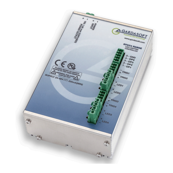
RTCC LED lighting controllers - User Manual Connections Section 13, Reference information for information about connection ratings Power supply In the unlikely event of a fault in the RTCC, the maximum power dissipation in the unit can be: Power supply voltage x Max current delivered by power supply Either limit the power supply output current so that the RTCC cannot dissipate more than 30W, or mount the unit in a fire enclosure. - Page 19 Ensure you set the current or voltage rating of your light before you connect it, see Section 8, Lighting setup. The connectors fitted to , an RTCC series controller are shown in the illustrations below. You should refer to Section 6.3, Trigger inputs for the pin allocations of the trigger connectors, and Section 6.4, Digital outputs...
-
Page 20: Trigger Inputs
RTCC LED lighting controllers - User Manual Trigger inputs The trigger inputs are opto-isolated 3V to 24V input, drawing a minimum of 3mA. The table below describes the pin allocations for the RTCC controllers’ trigger connectors: Connector Connector ET12 ET34 TRIG1 – TRIG3 –... -
Page 21: Power Output
RTCC LED lighting controllers - User Manual 12V Power output RTCC controllers have one 12V power supply output. It can supply up to 1A at 12V for powering cameras and other devices. Do not connect inductive loads or devices that take large peak currents. Do not exceed the current rating as these outputs are not fused. - Page 22 RTCC LED lighting controllers - User Manual Würth part Farnell/Newark Connector Description number part number 2W screw terminal Power input 691-351-500-002 164 1952 free socket 4W screw terminal Trigger input 691-361-100-004 184 1351 free socket 2W screw terminal 12V output 691-348-500-002 free plug 5W screw terminal Digital outputs...
-
Page 23: Lighting Controller Operation
Gardasoft Vision. Controllers in the RTCC series are set up using an Ethernet port or serial port. The set up is non-volatile, so the RTCC resumes the same operation after a power cycle. -
Page 24: Continuous Output, Switched Output, Selected Output
RTCC LED lighting controllers - User Manual 7.1.1 Continuous output, switched output, selected output Mode Trigger input Output Continuous Unused Output is on Switched Trigger = off Output is off Trigger = on Output is on Selected Trigger = off Output is continuous brightness 2 Trigger = on Output is continuous brightness 1 Pulsed... -
Page 25: Fault Detection
RTCC LED lighting controllers - User Manual For example, if the brightness is set to 250%, then the RTCC does not allow pulses greater than 10ms long. With 10ms pulses, if a trigger occurs within 50ms of a previous trigger (so that the duty cycle would be greater than 20%) the trigger is ignored. -
Page 26: Cold Start
RTCC LED lighting controllers - User Manual Comms error Reason number Current output is too low. This may be Err 21 because the light has become disconnected. The lighting required more than the Err 22 maximum available current for the voltage rating. Current output is not what was Err 23 expected. -
Page 27: Lighting Setup
RTCC LED lighting controllers - User Manual Lighting setup The rating of the light must be set by the user. This rating is the supply to the lighting that should be used to get 100% continuous brightness from the light. The RTCC is compatible with both current and voltage rated lighting. -
Page 28: Timing Controller Operation
RTCC LED lighting controllers - User Manual Timing controller operation The RTCC timing controller has four digital inputs (through the trigger input connections), four digital outputs, and twelve virtual outputs (see Section 9.4, Virtual outputs). All outputs operate independently and are configured separately. -
Page 29: Output Modes
RTCC LED lighting controllers - User Manual Output Modes Each output operates independently. By combining which outputs are triggered by which inputs, and which mode each output is in, it is possible to configure complex sequences of operation. Multiple outputs can be triggered by one input to give synchronous operation, or from separate inputs to give asynchronous operation of different functions. - Page 30 RTCC LED lighting controllers - User Manual The following operating modes are available for each output. The Mode Number is used for configuration commands sent using Ethernet. Mode Mode Operation name Set Low The output is set to off or logic 0. If the output is (Off) inverted (flag O is set) then the output is logic Set High...
- Page 31 RTCC LED lighting controllers - User Manual Mode Mode Operation name Buffer T Buffer an input by making the output the same signal as the input. If the Gate Input parameter (buF) is set, then the gate input signal enables the output –...
-
Page 32: Burst Mode
RTCC LED lighting controllers - User Manual Mode Mode Operation name D-Type D-type latch. When a leading edge is received Latch on the trigger input, the gate input signal is (dLA) latched and is used to set the output. RS Latch Edge triggered RS latch. -
Page 33: Ethernet Message Flag (E)
RTCC LED lighting controllers - User Manual Operation Operation Flag Flag value name when flag = 0 when flag = 1 Triggers are ignored FIFO output mode. until output pulse is Multiple triggers are complete. queued up. See Section 9.3.2, FIFO flag Resync mode disabled. -
Page 34: Resync Flag (R)
RTCC LED lighting controllers - User Manual 9.3.3 Resync flag (R) Reject gate operation usually needs to be synchronised to the original product trigger. However image processing can take a variable length of time to complete, so rejects based on when the processing result is available cannot be accurately timed. -
Page 35: Trigger Timing Examples
RTCC for your own application. A blank configuration form (see Appendix A - Configuration sheet) is available for download from www.gardasoft.com. Synchronised camera and lighting An input trigger arrives at IP1 and the leading edge is used to pulse a light after 60ms, and then a camera exposure 0.5ms later. -
Page 36: Gated Pulses
RTCC LED lighting controllers - User Manual Gate Pulse Pulse Retrigger Output Mode Input Flags input delay width time 100ms 100μs 200ms 100μs Both outputs are set to pulse mode. Two different delays give the timing difference between the two cameras. Gated pulses A camera needs to be triggered at 25Hz continuously, except when IP1 is high to indicate that the machine has stopped. -
Page 37: Belt Position Triggering
RTCC LED lighting controllers - User Manual Belt position triggering On a conveyor with an encoder, a sensor detects product presence. There are two cameras which are to take an image at fixed distances along the belt. The camera trigger pulses must be fixed width for exposure control. The trailing edge of IP4 is used as the trigger. -
Page 38: Simple Fifo Mode
RTCC LED lighting controllers - User Manual Simple FIFO mode A sensor on IP1 detects the presence of a product . After a delay, OP1 triggers a camera. There may be several products between the sensor and the camera. The RTCC stores each of the triggers and then outputs a pulse after the correct delay. -
Page 39: Resync Mode
RTCC LED lighting controllers - User Manual Resync mode A sensor on IP1 detects the presence of a product . After a delay, OP1 triggers a camera. Image processing software processes the image (which can take a variable length of time) and then sends a pass/fail message to the RTCC. -
Page 40: Resync And Fifo Mode
RTCC LED lighting controllers - User Manual In this example, three product triggers were received. The camera was triggered using OP1. An Ethernet message with tag number 10 was sent to the host computer when the first trigger was received, but a reply was not received, so the product was rejected for fail-safe operation. -
Page 41: Ethernet Communication(Rtcc420)
You may need to ask your network administrator for advice about setting up the Ethernet connection. Ethernet set up is not affected by cold booting the RTCC. See Application note APP923 (available from www.gardasoft.com) for troubleshooting Ethernet problems. 10.1 Connection The Ethernet link uses a 10Base-T connection on an RJ45 connector. -
Page 42: 10.2.1 Dhcp
10.3 Automatic sensing All the features below are implemented in sample C++ source code available for download from www.gardasoft.com. The RTCC sends a message on three events: i. On power up ii. When an IP address is received or renewed by DHCP iii. - Page 43 RTCC LED lighting controllers - User Manual An enquiry message is a UDP packet from source port 30310, destination port 30311 with the message body ‘Gardasoft Search’ (8-bit ASCII, 13 characters). The message output by the RTCC is a UDP packet from source port 30311, destination port 30310.
-
Page 44: Webpage Configuration (Rtcc420)
RTCC's webpages. You can also type the controller’s IP address (displayed in GardasoftMaint) into your web browser, which will display the Main screen. GardasoftMaint software is available from www.gardasoft.com/Downloads. 11.1 Main page The main page (shown below) is the first to open when you access the RTCC's webpages. -
Page 45: Configuration Page
RTCC LED lighting controllers - User Manual 11.2 Configuration page There is one configuration page for each output channel, as shown below: You can set up all the parameters for each output channel. Pressing the Submit button updates the RTCC configuration and saves the changes to non-volatile memory. -
Page 46: General Setup Page
RTCC LED lighting controllers - User Manual 11.3 General setup page The General Setup page allows you to set up or clear the webpage's password and set up the internal trigger. You can also enter any Ethernet command from Section 12, Command configuration. -
Page 47: Command Configuration
RTCC LED lighting controllers - User Manual Command configuration The RTCC can be configured through the Ethernet connection using UDP or TCP/IP. You can download sample C++, C#, VB.NET code from www.gardasoft.com to allow configuration. 12.1 Ethernet configuration (RTCC420) For TCP, commands from a host should be sent to destination port 30313 with replies sent to destination port 30312. -
Page 48: 12.3.1 General Commands
RTCC LED lighting controllers - User Manual Note: parameters are in ‘USA/UK’ format so that a half is written ‘0.5’ not ‘0,5’. For example: Parameter Meaning 0.1 millisecond 200μs 200 microseconds 0.1s 0.1seconds 100ma 100mA 2.45A 2.45A 2300mA or 2.3A The command codes and their meaning are described in Section 12.3.1, General commands. - Page 49 RTCC LED lighting controllers - User Manual Save the settings to memory Once the settings are saved to memory they are retained when the unit is switched off. If this is not done, changes to the settings are volatile, and if the unit is switched off they revert to those in force when the last AW command was issued.
- Page 50 RTCC LED lighting controllers - User Manual When using Ethernet, use the following forms of the ST command: Reports the general settings. A typical output is: TM 1, TP 20.00ms Where: c = the input channel (1 to 2, 4, or 8 depending on model). This reports the settings for a single channel.
-
Page 51: 12.3.2 Lighting Channel Commands
RTCC LED lighting controllers - User Manual Set/Clear the Webpage Password EY asc1, asc2, asc3, asc4, asc5, asc6 This command sets the password required to access the webpages. If EY is entered on its own then the password is cleared. There are six optional parameters, which are decimal ASCII values for a password from one to six letters. - Page 52 RTCC LED lighting controllers - User Manual Set selected mode The output is set to selected mode with two brightness settings. RUc,s,t Where: c = output channel (1 to 4) s = brightness 1 setting in percent (s = 0 to 100) t = brightness 2 setting in percent (t = 0 to s) Set pulse mode The output can be set up to pulse on a trigger input.
-
Page 53: 12.3.3 Trigger Timing Commands
RTCC LED lighting controllers - User Manual Where: c = output channel (1 to 4) p = trigger input (1 or 2) 12.3.3 Trigger timing commands Show status command This command shows the operational parameters of the digital outputs. A typical output for the RTCC controller is: Encoder: 1 line OP1: MD=2, IP=1, GT=-, DL= 10.000ms, PL= 2.000ms, RT= 0.000ms, ioGefrp... - Page 54 RTCC LED lighting controllers - User Manual The gate input: 0 for none 1 to 4 for IP1 to IP4 5 to 8 for OP1 to OP4 Flags For example, the following command sets output channel 1 to pulse mode (Ptt), triggered by input 2, no gate input and flags = 2 (invert the output).
- Page 55 RTCC LED lighting controllers - User Manual Set Pass / Fail In Resync mode, this command returns the pass or fail state of image processing for a given trigger tag. SNc,t,p Where: Output channel number (1 to 4) Trigger tag number 1 for pass, 0 for fail For example, the following command gives output 1, trigger tag 76...
- Page 56 RTCC LED lighting controllers - User Manual If the 'O' configuration flag is set for an output, then the output is inverted. Show the state of an input Where: The input channel (1 to 4) This command returns if the input is logic 0, and if the input is logic 1.
-
Page 57: 12.3.4 General Command Summary
RTCC LED lighting controllers - User Manual 12.3.4 General command summary Command Example Effect Save changes. Clear configuration. Enable Ethernet messages. Clear any error conditions EY65,66 Set webpage password to 'AB'. Read the firmware version. VL1,0,0.5 Set the rating of channel 1 to 0.5A. RS2,65 Set channel 2 to 65% brightness continuous. - Page 58 RTCC LED lighting controllers - User Manual Command Example Effect ZR2,15 Set retrigger time to 15ms for channel 2. ZS2,3,4,0,0 Set channel 2 to Pulse TE with gate on IP4. ZB1,200 Set internal trigger period to 200ms. Set encoder mode to single input. Read the encoder count.
-
Page 59: Reference Information
RTCC LED lighting controllers - User Manual Reference information This section contains the specification for the RTCC and any restrictions on its use. Error and event codes are also listed. 13.1 Specification The RTCC range of controllers has a 2 amp option with a '-2' suffix, and a fast pulsing option with an 'F' suffix. -
Page 60: Restrictions
RTCC LED lighting controllers - User Manual 13.2 Restrictions The maximum output power for an RTCC4xx is 30W per channel or 50W total. The following timings and restrictions are applied whenever settings are saved (using the AW command). B.1 Continuous Mode The maximum output current is 3A (2A for an RTCC4xx-2). B.2 Switched Mode The maximum delay from a trigger input changing to the output current being turned on or off is 10us. - Page 61 RTCC LED lighting controllers - User Manual Pulse widths below 4ms are repeatable to within 1us and are not subject to variation even with other simultaneous events. Pulse widths above 4ms are repeatable to within 100μs and are subject to variation. —...
-
Page 62: Error Codes
RTCC LED lighting controllers - User Manual PTT mode pulses in the following conditions have higher priority and better timing: Delay = 0, pulse width <= 4ms Delay + pulse width <= 4ms and O flag not set For example with OP1 to OP2 all meeting the first condition: OP1 has delay 6.5μs +/-1μs OP2 has delay 6.5μs +/-1μs The reply time of a simple Ethernet command (for example the GT... -
Page 63: Fatal Error Codes
RTCC LED lighting controllers - User Manual Error number Reason The requested output current requires too high a Err 43 voltage. Err 36 The output is short circuit. Err 42 The output current is too high. The voltage required for the lighting has increased Err 37 too much. - Page 64 RTCC LED lighting controllers - User Manual Event number Reason An error has occurred. The error code is given by 1 to 127 the event number. This event is generated in Resync mode and is formatted as Evt10,xxx where xxx is the ID tag for the current product.
- Page 65 RTCC LED lighting controllers - User Manual This page is left blank for your notes: — —...
- Page 66 RTCC LED lighting controllers - User Manual Issue v002 - June 2017 © Copyright 2017 Gardasoft Vision Ltd Gardasoft LLC Gardasoft Vision Ltd Oak Ridge Road Trinity Court Weare Buckingway Business Park New Hampshire Cambridge CB24 4UQ UK 03281 USA tel: +44 1954 234970...