
Related Manuals for BlueVision BVC6100LM

Summary of Contents for BlueVision BVC6100LM
- Page 1 BlueVision Instruction Manual 4CMOS 4K RGBIR Line scan camera Model: BVC6100LM (Product code:9200015) Document revision v.01 BlueVision Ltd., Japan...
- Page 2 BVC6100LM Instruction Manual v.01 Revision note Date Revision Contents Note 2020/7/20 edition - 2 -...
-
Page 3: Table Of Contents
BVC6100LM Instruction Manual v.01 - Contents - Revision note ................- 2 - Preparation before using the camera ............ - 5 - 1. Necessary equipment ................- 5 - 2. Preparation for the shooting and basic settings of the camera ........ - 5 - 1. - Page 4 BVC6100LM Instruction Manual v.01 6.3.4 Setting by GAMMA curve ..............- 37 - 6.4 Configuration ................- 40 - 6.4.1 Window mode setting ............... - 40 - 6.4.2 1 Line memory ..............- 40 - 6.5 Matrix Enhancer ................- 41 - 6.5.1 Edge Enhancer ..............
-
Page 5: Preparation Before Using The Camera
BVC6100LM Instruction Manual v.01 Preparation before using the camera 1. Necessary equipment Camera:BVC6100LM Lens: M52 mount or F mount as an option Following lenses are available from Bluevison 20mm,24mm,28mm,35mm,50mm,105mm M mount and F mount Camera control soft: Sample soft ”3Sensor Control Toll” is available. -
Page 6: Installation Of Camera Control Tool "3Sensortool" And Initial Settings Of The Camera
Camera Control Tool “3SensorTool” and initial settings of the camera 2.1 Power the PC ON. 2.2 Create a new folder such as BVC6100LM. 2.3 Copy the exe file, ”3Sensor_Tool.exe” and the initial setting file, ”BVC6100.ini” to the folder ”BVC6100LM”. -
Page 7: General
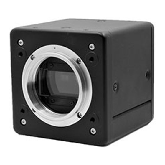
The BVC6100LM is a four COMS line sensor(7µm and 4096 pixels) camera using a prism optics to disperse to R,G,B and IR. The BVC6100LM has the line rate of 18030 lines per a second , rugged and compact housing, M52 lens mount and CameraLink Base configuration. - Page 8 BVC6100LM Instruction Manual v.01 range Typical : 0.58A (DC 12V input) Current Max : 0.62A (DC 12V input) consumption Lens mount M52 Mount 46.5mm tolerance: 0 ~ -0.05mm Flange back Optical axis accuracy Center ± 0.1mm(Max) MTBF 130000H ( at 25℃) Operating - 5℃...
-
Page 9: Parts Allocation And Functions
3. Parts allocation and functions 3.1 Parts allocation Bottom Front Rear ① Lens mount: Use M52 mount Lens The following are available by BlueVision BV-L1020-M 20mm F2.8 BV-L1024-M 24mm F2.8 BV-L1028-M 28mm F2.8 BV-L1035-M 35mm F2.8 BV-L1050-M 50mm F2.8 BV-L1105-M 105mm F2.8 ②... -
Page 10: Connector Pin Assignment
BVC6100LM Instruction Manual v.01 4. Connector Pin assignment 4.1 Image output connector Camera link1, Camera link2:12226-1100-00PL (3M) Pin assignmnet Digital I/F Camera Link 1 Camera connector Cable Name Cannel Link Signal Camera Signal Pair polarity - Pair polarity + Inner Shield... -
Page 11: Compatible Connector/Cable Ass'y
BVC6100LM Instruction Manual v.01 Compatible connector/Cable Ass’y Manufacture Type Note Camera side 12226-1100-00PL HPcL-MB-10M- HIRAKAWA Cable Ass’y HEWTECH CORP. Note 1.The applicable cable length of the mentioned cable assembly is from 1m to 10m. Note 2.If the cable is not compliant with CameraLink specifications, the cable length to communicate is restricted. -
Page 12: Dcin/Trigger Connector:hr10A-10R-12Pb(71)(Hirose)
BVC6100LM Instruction Manual v.01 4.3 DCIN/Trigger connector:HR10A-10R-12PB(71)(Hirose) Signal name Note DC10.8V~26.4V DC in N.C. N.C. N.C. N.C. Trigger N.C. DC10.8V~26.4V DC in ※ EEN (Exposure Enable) signal is used for the trigger of external light. It is +12V, Open Collector. -
Page 13: Signal Output
BVC6100LM Instruction Manual v.01 5. Signal Output Camera link bit allocation Port/Bit 8-bit x 4 10-bit x 4 12-bit x 4 Camera Link PinName Output Output Output Port A0 R[4] R[2] R[0] Port A1 R[5] R[3] R[1] Port A2 R[6]... - Page 14 BVC6100LM Instruction Manual v.01 (Output timing) 1 Pixel cycle TxCLK TxOUT3 TxOUT2 LVAL DVAL TxOUT1 TxOUT0 - 14 -...
-
Page 15: Camera Link Output Basic Timing Chart
BVC6100LM Instruction Manual v.01 5.2 Camera Link output Basic Timing chart Note 1: LVAL low level period in the above drawing is clock number when the trigger mode is OFF and the line period is the minimum value. Note 2: The time of Pixel and clock is the same. -
Page 16: Ob Output Mode "Off
BVC6100LM Instruction Manual v.01 5.2.2 OB output mode “OFF” It can be output Active Pixel of sensor in the period of LVAL Active. Full resolution Optical Black 16PIXEL LVAL Optica Black 16PIXEL Active Pixel ① VIDEO ② Pixel ③ Note 1... -
Page 17: Exporsure Control
BVC6100LM Instruction Manual v.01 5.3 Exporsure control 5.3.1 Trigger mode OFF、NO_SHUTTER_MODE Exporsure time of R、G、B、IR are 9.52us, All of Video output come out at the same timing when exposure is completed. Exposure period R,G,B,IR Video data R,G,B,IR L i n e R a t e <Command>... -
Page 18: Trigger Mode On、Shutter_Select_Mode
BVC6100LM Instruction Manual v.01 5.3.3 Trigger mode ON、SHUTTER_SELECT_MODE Exposure start timing need to be set by each channels to be aligned all channels exposure end. The longest exposure time setting channel start exposure when External trigger has been input.。 Each channels exposure start time are vary to output of all video at the same timing. -
Page 19: Trigger Mode On、Triggerwidth
BVC6100LM Instruction Manual v.01 5.3.4 Trigger mode ON、TriggerWidth Exposure time = External trigger active period All channels of exposure timing are set as same timing. VIDEO output will be executed when External trigger active period (Exposure period) is ended. Trigger Polaity “High”: Trigger High level period = Exposure Active period. -
Page 20: Camera Setting
BVC6100LM Instruction Manual v.01 6. Camera setting 6.1 Operation mode, Sensitivity setting Operation Line rate mode Exposure time Gain Black level White balance Data save and Readout Exposure time Pulse output - 20 -... - Page 21 BVC6100LM Instruction Manual v.01 6.1,1 Operation mode Camera sync mode and Exposure are set by 「Trigger」、「Source」、「Polarity」 Possible combination for Sync and Exposure Trigger Source Polarity 動作内容 Sync Exposure mode NoShutterMode invalid invalid Internal By line cycle ShutterSelectMode ExternalTriggerOF invalid Internal...
- Page 22 BVC6100LM Instruction Manual v.01 「Polarity」: Select polarity of external trigger signal Active Low : Exposure is started at falling down edge of external trigger in Shutter Select Mode Exposure time is set by the LOW level period of extrnal trigger...
-
Page 23: One Push Auto White Balance
BVC6100LM Instruction Manual v.01 6.1.4 Gain Able to set by each R,G,B,IR. There is the setting box at 「Gain」 in the camera control tool. 4 windows, R(left), G(left middle), B(right middle), IR(right) Gain setting range:512~6400 Ex):0dB:1600, 12dB:6400, -3dB:512 Gain setting resolution: 1step= 1/1600 6.1.5 Black level... - Page 24 BVC6100LM Instruction Manual v.01 1) Select from R、G、B、IR 2) Polarity selection Note1 : In case of multiple EEN selection, EEN comes out by the longest exposure time of R,G,B or IR. TRIGGER Exposure Rch Exposure Gch Exposure Bch Exposure IRch...
-
Page 25: Save /Readout The Setting
BVC6100LM Instruction Manual v.01 6.1.8 Save /Readout the setting Select 「User Set 1」 or「User Set 2」 in User set. Data Readput 1.Select 「Set up」 tub 2.Select 「User Set 1」 or 「User Set 2」 where camera setting data is saved. 3.Click 「LOAD」... -
Page 26: Set Up」 For Shading, Dsnu
BVC6100LM Instruction Manual v.01 6.2 「SET UP」 for Shading, DSNU Filter Binning DSNU LVAL leng Shading Configuration Test Pattern Lateral chromatic aberration correction - 26 -... - Page 27 BVC6100LM Instruction Manual v.01 6.2.1 DSNU This command adjusts the uniformity of the dark signal. When it is adjusted, put the lens cap on the lens. Click「ADJUST」 Click「SAVE」 Click「LOAD」 No Adjustment :OFF Factory Default :Default setting Select 「User Set 1」or「User Set 2」...
- Page 28 BVC6100LM Instruction Manual v.01 6.2.2 Shading Shading correction (compensation) due to the Optics Before After Click「ADJUST」 Click「SAVE」 Click「LOAD」 No Adjustment : Shading OFF Factory Default :Default Select 「User Set 1」or「User Set 2」 Procedure 1) capture white flat color object 2) Select「No Adjustment」 in 「Shading」 menu and click 「LOAD」. Shading will be ”OFF”.
-
Page 29: Filter
BVC6100LM Instruction Manual v.01 6.2.3 Filter LPF (structured by FIR Filter) Noise reduction at the high band area however MTF would be worse. Default is OFF. DNR(Digital Noise Reduction structured by Median Filter) Default is OFF. 「DNR」-「On」 It is 3dB around is improved for Noise. -
Page 30: Test Pattern
BVC6100LM Instruction Manual v.01 6.2.7 TEST Pattern Test pattern is available for color bar or horizontal gradation. <Color Bar> Output order of the color bar for R,G,B ch is started from White->Yellow-> Cyan->Green-Mazenta->Red->Blue->Black In IR ch, 128LSB of Grey level is output. -
Page 31: Lateral Chromatic Abberation Compensation
BVC6100LM Instruction Manual v.01 6.2.8 Lateral Chromatic abberation compensation This function can compensate the lens aberration(Lateral color abberation correction). Using G channel as the reference, it compensates how many pixles of R channel and/or Blue, IR channel are shifted forwards or backwards. - Page 32 BVC6100LM Instruction Manual v.01 Aberration sets ”ON” when all input would be completed 2. Semi Auto setting 1) Aberration, OFF. 2) Click 「DEFAULT」 and Input checking position of L-END、LEFT、RIGHT、R-END values as default. It depends on Lens and WD, see the following table.
-
Page 33: Lut、Gamma Setting
BVC6100LM Instruction Manual v.01 6.3 LUT、GAMMA setting Output will be varied by LUT, it is able to set by R, G, B separately. Output will be Linear(γ=1.0) in case of LUT-OFF. It is appled all 3 channels. Select LUT「ON」 Data input of R, G, B : Select at 「Channel」. -
Page 34: Input One By One
BVC6100LM Instruction Manual v.01 Table data input 6.3.1 Input one by one 1) Use 「Table」 example case (Input- 1 and Output -132) ① Switch 「LUT」 to 「ON」 ② Select 「Channel」 from「Red」「Green」「Blue」 or 「IR」. ③ Input 「Table」 for the input value ad the output value. - Page 35 BVC6100LM Instruction Manual v.01 4) Open LUT data, that Data will be applied. (Example for the name of table data) The following Red circle part of message and ”>” in 「Communication Monitor」will be popped out when that data is appled.
-
Page 36: Setting By Lut Curve
BVC6100LM Instruction Manual v.01 LUT/ Gamma curve data input Setting by LUT curve 6.3.3 LUT data and setting are able to use by LUT curve in [LUT/GAMMA] tub as follows. Select each LUT curve in Gamma the drop down list for individual setting. -
Page 37: Setting By Gamma Curve
BVC6100LM Instruction Manual v.01 Select ”ON” in LUT drop down list. LUT data will be applied in the captured image. It is able to change LUT curve in 「 LUT 」 「 ON 」 mode. Click 「SAVE」 to save LUT data in the camera. - Page 38 BVC6100LM Instruction Manual v.01 Then select ON in LUT drop down list. LUT data will be appled. It is able to change LUT curve in 「LUT」 「ON」 mode. Click 「SAVE」 to save LUT data in the camera. - 38 -...
- Page 39 BVC6100LM Instruction Manual v.01 GAMMA setting window 「Gamma」 Select LUT curve 「SAVE」 LUT data saving 「 LUT 」 LUT ON/OFF Spline:LUT curve setting : GAMMA 1.0 : GAMMA 0.6 0.45 : GAMMA 0.45 Select R、G、B or IR individually in 「Color」...
-
Page 40: Configuration
BVC6100LM Instruction Manual v.01 6.4 Configuration Window mode setting and Save/Readout for 1 Line image data. 1 Line memory setting Window mode setting 1 Line memory 6.4.1 Window mode setting 「Sub-Window」 「On」 the center of 2048pixels out of 4096 are output. -
Page 41: Matrix Enhancer
BVC6100LM Instruction Manual v.01 6.5 Matrix Enhancer Matrix/Enh tab for edge enhancement and color correction setting. Edge Enhancer High Pass Filter Color Matrix 6.5.1 Edge Enhancer Edge enhancement by gain multiply for less than 3pixels range of rising up /falling down signal. -
Page 42: Hpf (High Pass Filter)
BVC6100LM Instruction Manual v.01 0~255 「Core」: To avoid Noise increasing due to Edge enhancement by the detection level setting of Edge signal. 0: detect all of edge signal and do edge enhancement by 「GAIN」 setting. 8bit output: 0.0625/step 10bit output: 0.25/step... - Page 43 BVC6100LM Instruction Manual v.01 「GAIN」 : 0:x 1.05 1:x 1.13 2:x 1.27 6.5.3 Color Matrix Enable for gain input by each in 「MODE」 「On」. See the following formula. Default: KRR=KGG=KGB=1.000 (no color correction condition) Gain range: ±2.000 times (Max), 0.001 step <Fomula>...
-
Page 44: Information
BVC6100LM Instruction Manual v.01 6.6 Information Baud rate, Model name, Firm FPGA Version and Serial No are shown. Baud Rate 115200 : Serial communication rate is set by 115200bps. 9600 : Serial comminication rate is set by 9600bps. When it is changed , the following window comes out and click (Y) to be commpleted. -
Page 45: File
BVC6100LM Instruction Manual v.01 6.7 File In the file menu, the camera setting data can be saved or loaded in the txt file format. ② Load from File ① Save to File ③ Command file writing ④ Field update Save To File ①... -
Page 46: Tool
BVC6100LM Instruction Manual v.01 6.8 Tool In this screen, it is used to supprt command input and save. 1) Monitor This is to input commands by TEXT. Communication Monitor window comes out when “Monitor” is clicked. After input, OK or Error, etc... will be come out. -
Page 47: Help/About
BVC6100LM Instruction Manual v.01 6.9 Help/About When “About” is selected in Help menu, the control tool version will be indicated. - 47 -... -
Page 48: Serial Communication
BVC6100LM Instruction Manual v.01 7. Serial communication Serial communication protocol The camera control tool “3Sensor Tool” to be provided is used to control a camera using a serial communication protocol. Serial communication protocol Parameter Setting value BIT/sec 115200bps Data Bit... -
Page 49: Command List
BVC6100LM Instruction Manual v.01 Command List Item Command Parameter Description ExposureTime Acquire the current exposure time to be set exp␣[ChNum] for each channel exp ␣ [ChNum] ␣ [PRAM [ChNum]: Set the exposure time[1us/1step] ※Exposure time(max) ①] r,g,b,ir 1 line cycle time ー 9.52μsec [PRAM①] Exposure time... - Page 50 BVC6100LM Instruction Manual v.01 shadingadjust Execute the Shading compensation [PRAM①] setting number shadingsave␣[PRAM①] Save the adjusting value for the Shading 1: Default compensation in [PRAM①] 2: User Set 1 2~3: for user, 1: for Factory setting 3: User Set 2 Access limit is set by control tool side.
- Page 51 BVC6100LM Instruction Manual v.01 abeleftposi␣[ChNum] ␣ [ChNum] sensor ch Set the LEFT position by [PARAM①] R、G、B、IR [PRAM①] [PRAM①] LEFT position 0~4095 aberightposi␣[ChNum] [ChNum] sensor ch Acquire the RIGHT position information for R、G、B、IR each channel [ChNum] sensor ch aberightposi␣[ChNum]␣ Set the RIGHT position by [PARAM①] R、G、B、IR...
- Page 52 BVC6100LM Instruction Manual v.01 User Set Userset Acquire the current camera setting number to be set userset␣[PRAM①] Set the camera setting by PRAM① [PRAM①] Setting number 0:Factory default setting (Cannot be changed) 1: User Set 1 2: User Set 2 [PARM①] Setting number...
- Page 53 BVC6100LM Instruction Manual v.01 eenpolarity EEN output polarity eenpolarity␣[PRAM①] [PRAM①] EEN Polarity Change EEN polarity by[PARA①] 0:Active low 1:Active high Sub-Window subwindow Sensor Window、Sub-sampling selection subwindow␣[PRAM①] [PRAM①] setting number OFF: All pixels readout 0:Off Window: the center of 2048pixels read...
- Page 54 BVC6100LM Instruction Manual v.01 enhancecore␣[ChNum] [ChNum] Range of threshold:12bit 0LSB~255LSB R、G、B、SWIR For edge detection ␣[PRAM①] [PRAM①] Less than threshold :No enhancegain 0~255 More than threshold: enhancegain activation by setting parameter HighPassFilter hpf␣[ChNum] Acuire hpf on/off setting by selected [ChNum] ch...
-
Page 55: Dimensions
BVC6100LM Instruction Manual v.01 8. Dimensions 4-M4,6mm depth 4-M4,6mm depth 4-M4,6mm depth - 55 -... -
Page 56: Spectral Response
BVC6100LM Instruction Manual v.01 9. Spectral response - 56 -... - Page 57 BVC6100LM Instruction Manual v.01 BlueVision Ltd., Japan 1-13-12 Shin-Yokohama, Kohoku Yokohama, 222-0033, Kanagawa, Japan TEL: +81(0)45-471-4595/ FAX: +81(0)45-471-4598 http://www.bluevision.jp - 57 -...
Need help?
Do you have a question about the BVC6100LM and is the answer not in the manual?
Questions and answers