Table of Contents
Advertisement
Quick Links
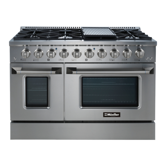
PROFESSIONAL SERIES
48" Freestanding Gas Range
Model No: GR-670
U S E R M A N U A L
Your satisfaction is guaranteed. If you are not completely
satis ed with our PROFESSIONAL SERIES 48" Freestanding Gas
Range and the results it brings, we insist that you let us know.
We'll help you make the Gas Range work for you, or we'll
refund your money.
Advertisement
Table of Contents

Related Manuals for Mueller GR-670

Summary of Contents for Mueller GR-670
- Page 1 PROFESSIONAL SERIES 48" Freestanding Gas Range Model No: GR-670 U S E R M A N U A L Your satisfaction is guaranteed. If you are not completely satis ed with our PROFESSIONAL SERIES 48" Freestanding Gas Range and the results it brings, we insist that you let us know.
- Page 2 GAS WARNING IF THE INFORMATION IN THIS MANUAL IS NOT FOLLOWED EXACTLY, A FIRE OR AN EXPLOSION MAY OCCUR, CAUSING PROPERTY DAMAGE, PERSONAL INJURY OR POSSIBLE DEATH. DO NOT STORE OR USE GASOLINE, A LIQUID PROPANE CYLINDER OR OTHER FLAMMABLE VAPORS AND LIQUIDS IN THE VICINITY OF THIS APPLIANCE. AN LIQUID PROPANE CYLINDER NOT CONNECTED FOR USE SHALL NOT BE STORED IN THE VICINITY OF THIS OR ANY OTHER APPLIANCE.
-
Page 3: Table Of Contents
CONTENTS IMPORTANT SAFEGUARDS HANDLING AND UNPACKING CORRECT USAGE CHILDREN TECHNICAL SAFETY COOKING SAFETY PARTS RANGE INSTALLATION DIMENSIONS CLEARANCES HOOD / COMPOSITE OVERLAY INSTALL LEVELING ANTI-TIP BRACKET ELECTRIC POWER SUPPLY REQUIREMENTS GROUNDING WIRING DIAGRAM GAS SUPPLY REQUIREMENTS CONNECT RANGE TO GAS SUPPLY COMPONENT PART ASSEMBLY BEFORE FIRST USE COOKTOP OPERATION... -
Page 4: Important Safeguards
This User Manual contains important information on how to install and set up your new range, safe use, and maintenance, as well as insights into the product features. READ ALL INSTRUCTIONS BEFORE INSTALLING AND OPERATING YOUR MUELLER PROFESSIONAL SERIES 48" FREESTANDING GAS RANGE FOR THE FIRST TIME. IF... -
Page 5: Children
CHILDREN ● Children should not be left alone or unattended in an area where the appliance is in use. ● Never allow children to sit or stand on any part of the appliance. ● CAUTION: Do not store items of interest to children above or at the back of the appliance. - Page 6 Gas must be installed by a qualified service technician in accordance with all applica- ble codes and requirements of the authority having jurisdiction. Before proceeding with any conversion, ensure the gas supply is shut off and the electrical power to the range is disconnected.
-
Page 7: Cooking Safety
yellow tipping should be restricted to the primary flame kernels only. Properly adjust- ed burners, indicated by a bluish rather than a yellow flame, will minimize incomplete combustion. Exposure to those substances can be minimized by venting with an open window or use of a ventilation fan or hood. ●... - Page 8 ● When using the oven, open the door carefully to allow hot air or steam to escape before placing or removing food. ● The Burner Grates supplied with the appliance must always be used, unless replacing with the Griddle. Never place cookware on the burner by itself. ●...
- Page 9 ● Do not use the ovens for frying. ● Do not use water on grease fires. Smother any fire or flame using a lid, close the oven door, or use a dry chemical or foam-type extinguisher. ● Do not flambé under an exhaust hood. Flames could be drawn up into the hood by the suction or the grease filters may ignite.
-
Page 10: Parts
PARTS Standard Double Burner Burner Griddle Burner Top Vent Gate Control Panel Oven 2 Light Switch Oven 1 Convection Light Fan Switch Switch Cool Air Oven 2-30’’ Intake Conventional DO NOT Convection/Broil OBSTRUCT Oven 1-18’’ Conventional Front Vent Panel INCLUDES: 4 Cast Iron Burner Grates 1 Porcelain Enameled Cast Iron Double-Sided Griddle 6 Standard Burner Caps... - Page 11 Oven 1-18’’ Oven 2-30’’ Conventional Conventional/Convection/Broil Burner BTU/H NG Orifice LP Orifice Position 6,000 1.07 0.74 FRONT LEFT (F/L) 20,000 1.36*2+0.73 0.89*2+0.53 FRONT MIDDLE LEFT (F/M/L) - DUAL 6,000 1.07 0.74 FRONT MIDDLE RIGHT (F/M/R) 20,000 1.36*2+0.73 0.89*2+0.53 FRONT RIGHT (F/R) - DUAL 9,000 1.36 BACK LEFT (B/L)
-
Page 12: Range Installation
RANGE INSTALLATION ● WARNING: Do not lift or carry the range by the oven handles. ● Remove and recycle packaging and keep out of reach of children. ● Before installing the range, you must locate and secure the included Anti-Tip Bracket Set for your range. -
Page 13: Clearances
CLEARANCES WARNING: The minimum distances given in these installation instructions are to combustible surfaces, and must be observed to ensure safe operation. Maximum depth for cabinets Minimum to cabinets on above either side of the range countertops 48" 13" 30" Minimum 13"... -
Page 14: Hood / Composite Overlay Install
HOOD / COMPOSITE OVERLAY INSTALL It is recommended that the unit be set under a powered, vented exhaust hood of suffi- cient size and capacity. WALL INSTALLATION ISLAND INSTALLATION Wood/ Composite Overlay Wood/ Composite Overlay Metal Hood Metal Hood 30" (762mm) min 30"... -
Page 15: Anti-Tip Bracket
ANTI-TIP BRACKET To prevent the range from tipping forward, the anti-tip bracket must be installed. WARNING: DO NOT OPERATE THE RANGE WITHOUT THE ANTI-TIP BRACKET IN PLACE. IF THE APPLIANCE IS ACCIDENTALLY TIPPED, THE WEIGHT OF THE RANGE MAY CAUSE SERIOUS INJURY. Right Bracket Screws... -
Page 16: Electric Power Supply Requirements
ELECTRIC POWER SUPPLY REQUIREMENTS ● Your range must be electrically grounded in accordance with local codes or, in the absence of local codes, in accordance with the National Electrical Code (ANSI/NFPA 70, latest edition). A copy of this standard may be obtained from the National Fire Protection Association. -
Page 17: Wiring Diagram
● Where a standard two-prong wall receptacle is encountered, it is the responsibility and obligation of the customer to have it replaced with a properly grounded three-prong wall receptacle by a licensed electrician. ● All cord connected appliances shall include instructions relative to location of the wall receptacle and a warning to the user to disconnect the electrical supply before serving the appliance. -
Page 18: Gas Supply Requirements
GAS SUPPLY REQUIREMENTS ● Installation and service must be performed by a qualified installer. ● The range has been equipped and adjusted for use with natural gas (NG) at manu- facture. ● For use with liquid propane (LP) gas, the range must be properly adjusted by a qual- ified installer. -
Page 19: Connect Range To Gas Supply
CONNECT RANGE TO GAS SUPPLY ● The range must be connected to a regulated gas supply. The supply line must be equipped with an approved external gas shut-off valve located near the range in an accessible location. Do not block access to the shut-off valve. ●... -
Page 20: Component Part Assembly
COMPONENT PART ASSEMBLY BURNER ASSEMBLY Align the small ignitor hole/indentation of the Burner Head to fit around the Ignit- er and place on the Burner Base. Center the Burner Cap/s on top of the Burner Head. The Burner Cap must be in a flat, horizontal position. - Page 21 BURNER GRATES ● There are 4 Cast Iron Burner Grates. Secure the grates vertically, side-by-side on top of the burners. ● Improper installation of the grates may result in scratching of the cooktop and/or poor combustion. ● Always use the Burner Grates, and never place cookware directly on the Burners. GRIDDLE The Griddle can be placed on the range Reversible Griddle...
-
Page 22: Before First Use
BEFORE FIRST USE CLEAN ● Remove any packaging and protective films. ● Remove any residue oil or grease from the manufacturing process: COOKTOP: Wash the removable parts (Burner Grates, Griddle, Burner Caps and Burner Heads) of the cooktop in a mild solution of warm water and liquid dish soap. Dry thoroughly. -
Page 23: Cooktop Operation
● Check ignition of oven burner. ● Visually check heating elements of both ovens. Carefully lift the panel on the interi- or floor of each oven. Turn on the ovens to check the heating elements heat fully. Turn off ovens and allow to cool before returning the floor panels. ●... - Page 24 When a flame is visible, keep the Burner Control Knob pressed and continue to turn the knob counterclock- wise to adjust the flame size. If the knob stays at ‘IGNITE’, it will continue to click. The burner can be continuously regulated between highest and lowest flame.
- Page 25 FLAME REGULATION Once the flame is ignited, rotate the Burner Control Knob to regulate the flame. ● To reduce the flames from a high to a low setting, push the corresponding knob in and turn counterclockwise. ● To increase the flames from a low to a high setting, push in and turn the Burner Control Knob clockwise.
-
Page 26: Griddle Operation
GRIDDLE OPERATION The Griddle offers a versatile cooking surface to cook many food items and allows for easy flipping with no side edges. The flat side is perfect for pancakes, bacon, eggs, French toast, hash browns, and hamburgers, while the grooved side it perfect to sear or char meats such as steaks or sausages. -
Page 27: Oven Operation
OVEN OPERATION BEFORE USING THE OVENS When using the appliance for the first time, the oven and broiler burners should be turned on to burn off any manufacture oils. See ‘BEFORE FIRST USE’ for further details. WARNING: Oven Vent Do not block the Top Vent of the range, nor the ducts of the door for cool air intake and exhaust. - Page 28 CONVECTION – OVEN 2 The convection function can be set on Oven 2 only. Heat is transferred from the heat- ing element in the bottom of the oven cavity to the oven cavity itself. The convection fan in the rear of the oven then circulates the heat. This convection process provides more even heat distribution throughout the oven cavity.
- Page 29 ● Preheating Preheating is suggested when searing rare steaks. (Remove any broiler pan before preheating with the infrared broiler as foods will stick on hot metal.) Preheat for approximately 2 minutes, or when the burner is deemed hot. Preheating is not neces- sary when broiling meat well-done.
-
Page 30: Care And Cleaning
CARE AND CLEANING The range and its components should be cleaned after each use to avoid build up of food residue and possible staining or discoloring. Only clean the parts listed in the following instructions. WARNING: To avoid the risk of burns or electrical shock, ensure that all burner controls are in the OFF position and that all components are completely cool before cleaning. - Page 31 ● Dry thoroughly before reassembly. Any wet ports will prevent the flame from ignit- ing. ● NOT dishwasher safe. Note: The surfaces of the burner parts and grates become slightly duller over time. This is normal and does not indicate any impairment of the material. PORCELAIN COOKTOP ●...
- Page 32 Oven Gasket IMPORTANT: Do not clean the oven gasket. The fiberglass material cannot withstand abrasion and rubbing and moving the gasket may compromise the door seal. OVEN DOOR ● Clean with a solution of mild liquid dish soap and warm water and a damp sponge. Rinse well.
- Page 33 CONTROL PANEL AND KNOBS, DOOR HANDLE ● Clean with a solution of mild liquid dish soap and warm water and a damp cloth. Wipe in the direction of the grain. ● Do not use abrasive cleaners or scrubbers; they will permanently damage the finish and printed surfaces.
-
Page 34: Troubleshooting
TROUBLESHOOTING Should you encounter any issues with your range, refer to the following table for possible troubleshooting solutions. ISSUE POSSIBLE CAUSE SOLUTION Have oven connected to a properly sized electrical Oven is not connected to power supply by a qualified the electrical power. -
Page 35: Specifications
Low gas supply pressure. Contact gas company. Burner flame goes out at low setting Air intake holes around Remove obstruction. burners are obstructed. No Power Supply (Oven Check that the circuit breaker Oven will not heat hasn’t tripped and there is no light and Igniters do not power outage in your area. -
Page 36: Warranty
1-Year Limited Warranty This product is warranted to be free from defects in material and YEAR workmanship under normal use and service for one year from the date of the original purchase with the receipt. The manufacturer's obligation shall be limited to repairing or replacing any part of the product that is defective.
Need help?
Do you have a question about the GR-670 and is the answer not in the manual?
Questions and answers
Is it possible to obtain a rear panel view with dimensions of this product? We need to know where the gas & electrical hookups are for potential conflict with a recessed pocket door alcove. Thanks.