
Summary of Contents for Idea ISW-10 SF1-DN1
- Page 1 INTELLIGENCE INVERTER SPLIT HEAT PUMP INSTALLATION MANUAL MODEL: ISW-10, 15, 18, 24, 32 SF1-DN1 outdoors ISW-10, 15, 18, 24, 32 SF1-SPM indoors...
- Page 2 Dear user: Thank you for using our products! You are using an air source heat pump unit. There are certain requirements for the installation, use and maintenance of the unit. Properly installed, used, and maintained, your hot water unit will have a reduced failure rate and a significant increase in service life.
-
Page 3: Table Of Contents
CONTENT I OVERVIEW ........................................- 4 - 1.1 TYPE & MODEL ........................................... - 4 - 1.2 COMPONENTS ..........................................- 4 - 1.3 SCHEMATIC DIAGRAM OF SYSTEMS ................................... - 5 - 1.4 COOLING OPERATION ......................................... - 5 - 1.5 HEATING OPERATION ......................................... - 6 - 1.6 DEFROST OPERATION ......................................... -
Page 4: I Overview
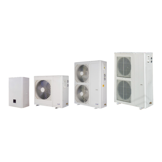
I OVERVIEW This Part mainly introduces the classification and model, naming rules, main components, working principle, transportation and storage environment requirements of air source heat pump heating and cooling units (hereinafter referred to as "units"). 1.1 TYPE & MODEL This series is including two types –Low temperature heating units & Low temperature heating and cooling units 1.2 COMPONENTS The unit includes compressors, finned tube heat exchangers, fans, controllers, expansion valves, plate... -
Page 5: Schematic Diagram Of Systems
1.3 SCHEMATIC DIAGRAM OF SYSTEMS Figure 1-1 1.4 COOLING OPERATION 1. After compression by the compressor, the low-temperature low-pressure gaseous refrigerant becomes a high-temperature high-pressure gaseous refrigerant. After being discharged from the compressor exhaust pipe, it enters the condenser (air-side heat exchanger) through the four-way reversing valve. -
Page 6: Heating Operation
1.5 HEATING OPERATION 1. The working fluid, in its gaseous state, is pressurized and circulated through the system by a compressor, and then go into the heat exchanger through the fore-way reversing valve. The unit to release heat though the water, and the refrigerant is condensed into a high pressure liquid. 2. - Page 7 Heating capacity(min-max) 7.8(3-8) 12.2(5-13) 15(4-16) 19(5-20) 25(5-27) (kW) Heating input 2.32 3.60 4.65 6.80 7.70 A2W45 power(kW) Rated current (A) 11.00 12.00 3.36 3.39 3.23 3.28 3.25 Cooling Capacity/EER 7/2.81 11/2.8 14/2.75 19/2.7 25/2.75 (kW) A35W7 Rated Cooling Input Power/Current(kW/A 2.5/11.3 3.93/8 5.0/9.5...
-
Page 8: Environmental Requirements
1.8 ENVIRONMENTAL REQUIREMENTS 1.8.1 OPERATING ENVIRONMENT The operating environment requirements of the unit are shown in Table 1-1. ITEM REQUIREMENT INSTALLATION LOCATION Installation method: horizontal installation AMBIENT TEMPERATURE Outdoor: -25 °C ~ +43 °C ENVIRONMENT HUMIDITY Outdoor: 5%RH~95%RH 220V±10%/1N~/50Hz;380V±10%/3N~/50Hz; RUNNING POWER Not more than 1000m. -
Page 9: Installation
II INSTALLATION This Part describes the mechanical installation of the unit, including transportation, unpacking inspection, installation layout, and installation procedures, etc. EQUIPMENT HANDLING, UNPACKING, INSPECTION 2.1 TRANSPORTATION & HANDLING Choose a road with better conditions to prevent excessive bumps when transporting. The tilt angle of the unit should be kept within the range of 75 °... - Page 10 Lifting & installation: (Figure 2-3) The strength of the lifting cable should be 3 times larger than the weight of the unit. Check and ensure that the lifting hook is fastened to the unit, and the lifting angle should be greater than 60°.
-
Page 11: Unpacking
NOTE: Do not stand under the unit when lifting. Add fabric between the unit and the cable to prevent damage to the unit. 2.2 UNPACKING Try to move the heat pump to the nearest place to the installation site, and then remove the packaging. Unpacking steps: 1. -
Page 12: Selection Of Installation Sites
● Confirm that the leakage protection switch is installed. The leakage protection switch must be installed, otherwise it may cause electric shock. ● Connect the cable correctly. If the cable is connected incorrectly, electrical parts may be damaged. ● DO NOT operate the unit near flammable materials (such as paint, paint, gasoline, chemical reagents, etc.) to prevent fire or explosion. -
Page 13: The Arrangement Spacing Of The Units
2.7 THE ARRANGEMENT SPACING OF THE UNITS Recommended installation spacing diagram for outdoor unit (unit: mm) Figure 2- 4 Recommended installation spacing diagram for unit installation NOTE: ● Required service & water pipes connection space when installing the unit. ● If there are obstacles in front of the air outlet of the unit, please make sure that the obstacles are more than 2000 mm from the air outlet. -
Page 14: System Installation Layout
2.8 SYSTEM INSTALLATION LAYOUT 2.8.1 OVERALL LAYOUT OF THE HYDRAULIC SYSTEM For hot water and floor heating is shown in the figure below. For heating/cooling is shown in the figure below 2.8.2 INDOOR UNIT AND OUTDOOR UNIT CONNECTION PIPE CONNECTION 1, Use the connection pipe to connect outdoor unit and indoor unit together. - Page 15 (Pic 1) 2. Remove the head nut of stop valve from the indoor unit and the outdoor unit .(see pic2,3) (pic2,3) 3. Drip a few frozen oil onto the copper nut of the connecting pipe and screw it to the stop valve’s joint of the indoor unit and the outdoor unit and tighten with a wrench .
- Page 16 (pic4、5) Leakage detecting: Use a wrench to remove the head nut of needle valve from the outdoor unit’s stop- 18 - valve. (pic 6) 5, Same operation to connect with the indoor units. After the leakage detecting and vacuuming are completed, then open the stop valve of the indoor unit (See Pic7,8).
- Page 17 completely open the stop valve of indoor unit before starting the operation. (Pic 7, 8) 6, Vacuumize: (1),Equipment: vacuum pump, pressure gauge,Allen wrench (2),Discharge the refrigerant added to the connecting pipe when doing leakage detecting . (3), Use a hexagon socket to completely unscrew the outdoor unit’s stop valve counterclockwise, draw a vacuum from the needle valve of the outdoor unit’s stop valve.(Pic 9)...
- Page 18 (Pic10,11) 8, After the vacuum is acceptable, open the stop valve of the outdoor unit (See Pic12,12). It is necessary to use the hexagonal counterclockwise to completely open the stop valve of indoor and outdoor unit before starting the operation. Let the refrigerant go through the whole system.
-
Page 19: Minimum Capacity Of The Water System
Note: For installation related to the water pipe part: ● Install a valve at the highest point of each water circulations for releasing air from water system. ● A Y-shape filter is very important in front of circulating water pump of heat pump. ●... - Page 20 Figure 2-6 Because the floor heating capacity of the floor heating system is large, the system temperature stability is greatly guaranteed, and this point can be ignored. For commercial water system design, it should be checked whether the water capacity of the calculation system meets the thermal stability requirements of the system.
- Page 21 XD-05BSPM - 21 -...
-
Page 22: Unit Installation
XD-06BSPM Figure 2-8 Unit(mm) 2.10 UNIT INSTALLATION 2.10.1 INSTALLATION SPACE Note As the unit will produce condensate ,water leakage may will cause damage to other equipment nearby. So, drainage pipe must be provided during installation. - 22 -... -
Page 23: Maintenance Space Requirements
1. To ensure the normal operation of the unit, try to choose a spacious space as the installation site of the unit; 2. Avoid placing multiple outdoor units close together to avoid cross-air flow, unbalanced loads, and competitive operation; 3. When installing on the top of the building, pay attention to protecting the waterproof layer and complying with relevant local regulations. -
Page 24: Electrical Installation
III ELECTRICAL INSTALLATION This chapter introduces the electrical installation of the unit, including tasks, installation precautions, connecting power cords, and installation inspections. 3.1 TASK INTRODUCTION AND PRECAUTIONS 3.1.1LINES TO BE CONNECTED AT THE INSTALLATION SITE 1.Power cable 2.Out put control line 3.1.2 INSTALLATION PRECAUTIONS ●... - Page 25 Model ISW-10SF1 ISW-24SF1 ISW-32SF1 ISW-15SF1 ISW-18SF1 220V/1N~/50H Power source 380V/3N~/50Hz Main switch capacity/leakage protection device/fuse(A) Power cord size Ground wire size(mm There are total 3 connecting cables between indoor and outdoor machines, including the Water pump connecting wire (220V/50Hz, 7m can be connected), the wire controller line (4-core, 10 meters can be connected), and the temperature probe connecting line (6-core, 7 meters can be connected).
- Page 26 The three kinds of wires are in 1-1 mapping relationship with the connecting terminals. The connecting methods are as follows 1. Connect the circulate water pump wire to the wiring terminals(1 or 2) of the outdoor machine and the indoor machine, as shown in the figure below. Outdoor Terminal Indoor Terminal 2.
- Page 27 Outdoor Indoor 3. Connect the the Temperature Probe to the Temperature Probe wiring terminal of the outdoor machine and the indoor machine, as shown in the figure below. Outdoor Indoor 4. After the above 3 cables are connected, connect the power cable to the outdoor machine terminal, as shown in the following figure.
-
Page 28: Unit Wiring Requirements
Outdoor 3.3 UNIT WIRING REQUIREMENTS 1. Power supply and control lines not connected to the electric control box are not allowed to pass through the electric control box. Otherwise, electromagnetic interference may cause the unit and control devices to malfunction or even be damaged, and will lose efficacy. 2. - Page 29 1. The power supply voltage and frequency are the same as the rated voltage and frequency on the equipment nameplate. 2. There is no open circuit or short circuit in the electrical circuit of the system. 3. The power cables and ground cables to the disconnect switch, the unit are connected. 4.
-
Page 30: System Trial Operation
IV SYSTEM TRIAL OPERATION This chapter introduces the system trial operation, including the preparation work of the mechanical, water system, and electrical parts before start up. 4.1 PRECAUTIONS BEFORE TRIAL OPERATION ● Trial operation can only be performed after electrical safety inspection. ●... -
Page 31: Trial Operation
Safety devices meet the requirements Connection of operation panel meets the requirements 4.3 TRIAL OPERATION Use the operation panel to control the unit operation, and check the following items according to the operating instructions: 1. Whether the operation panel switch is normal. 2. -
Page 32: Controller Operation Instructions
CONTROLLER OPERATION INSTRUCTIONS 5.1 OVER VIEW ◎ The chip is developed and designed for inverter heat pump, the main features are as follows: There are heating and cooling operation modes; The operating parameters and setting parameters of the system can be displayed and changed, which greatly facilitates user debugging and installation;... - Page 33 Icon introduction: 1. Heating mode, display symbol " " 2. Cooling mode, display symbol " " 3. Display " " when the pump is running 4. Display " " when the compress is running 5. When defrosting, " " is displayed, indicating defrosting operation 6.
- Page 34 Key operation instructions: 1. " " key: Short press “ ” as the exit key and return to the main page. In the main interface, long press the " " button for 3 seconds to turn on/off. 2. " " mode key: In the power-on state, press and hold "...
- Page 35 Defrost entry temp -15℃~-1℃ -1℃ Defrost time 5MIN~20MIN 12MIN Defrost exit temp 1℃~40℃ 20℃ The temp difference 1 between 0℃~15℃ 7℃ ambient and coil when defrosting The temp difference 2 between 0℃~15℃ 5℃ ambient and coil when defrosting Defrost ambient temp 0℃~20℃...
- Page 36 Main EEV hot water initial opening 00 0~480 350 T≥25℃ Main EEV hot water initial opening 01 0~480 300[10,25) Main EEV hot water initial opening 02 0~480 250[-10,10) Main EEV hot water initial opening 03 0~480 200 T<-10℃ Main EEV heating automatic 0~480 80 ambient tempT≥14℃...
- Page 37 Auxiliary EEV manual steps 20~450 EVI electromagnetic expansion valve 11℃~45℃ 11℃ turn on temp Auxiliary EEV exhaust proportional coefficient Auxiliary EEV exhaust differential 0~180 coefficient Auxiliary EEV superheat proportional coefficient Auxiliary EEV superheat differential 0~180 coefficient Auxiliary EEV adjustment cycle 10~20 Auxiliary EEV target exhaust temp 70~120...
- Page 38 Auxiliary EEV heating initial opening 0~480 50[-5,4) Auxiliary EEV heating initial opening 0~480 50[-10,-5) Auxiliary EEV heating initial opening 0~480 50[-16,-10) Auxiliary EEV heating initial opening 0~480 60[-23,-16) Auxiliary EEV heating initial opening 0~480 60 T<-23℃ Auxiliary EEV hot water initial opening 0~480 T≥25℃...
- Page 39 Auxiliary EEV opening under defrost 0~480 Auxiliary EEV opening under cooling 0~480 Auxiliary EEV hot water automatic 0~480 80 T≥25℃ adjustment lower limit 00 Auxiliary EEV hot water automatic 0~480 100[10,25) adjustment lower limit 01 Auxiliary EEV hot water automatic 0~480 120[-10,10) adjustment lower limit 02...
- Page 40 (standby) Enthalpy valve exhaust 75℃ 50~125℃ 75℃5 T≥25℃ temperature under hot water (standby) Enthalpy valve exhaust 75℃ 50~125℃ 75℃[10,25) temperature under hot water (standby) Enthalpy valve exhaust 50~125℃ 60℃ [-10,10) temperature under hot water (standby) Enthalpy valve exhaust 50~125℃ 60℃ T<-10℃ temperature under hot water (standby) Enthalpy valve exhaust...
- Page 41 difference 0~125℃ 34℃ [-5,4) Auxiliary EEV heating exhaust temp 0~125℃ 40℃ [-10,-5) difference 0~125℃ 40℃ [-16,-10) Auxiliary EEV heating exhaust temp 0~125℃ 40℃ [-23,-16) difference 0~125℃ 40℃ T<-23℃ Auxiliary EEV hot water exhaust temp 0~125℃ 35℃ T≥25℃ difference Auxiliary EEV hot water exhaust temp 0~125℃...
- Page 42 heating Maximum speed 6 of DC motor under 0~1000 [-16,-10) 900 heating Maximum speed 7 of DC motor under 0~1000 [-23,-16) 900 heating Maximum speed 8 of DC motor under 0~1000 T<-23℃ heating 0~30 Heating Tw-Tp(Tlp)target value 1 T≥14℃ 0~30 Heating Tw-Tp(Tlp)target value 2 [9,14) 0~30...
- Page 43 Maximum speed 4 of DC motor under 0~1000 T<25℃ 500 cooling mode Heating valve function selection 0 not allowed / (stand by ) 1 allow to turn on Four-way valve polarity Power when cooling 1: Power when heating The ambient temp when electric heating turns -30℃~20℃...
- Page 44 Compressor actual frequency Low pressure sensor gauge measured(bar) pressure value(R410 gas) High pressure sensor gauge measured(bar) pressure value(R410 gas) DC Motor 1 speed DC Motor 2 speed Low pressure pressure conversion temperature High pressure pressure conversion temperature “ ” Setting button Clock settings: Press the "...
- Page 45 6. Forced defrosting: Press the " " and " " keys to enter the forced defrost mode. When entering defrost, " " is displayed. 7. Frequency parameter setting Long press the " " + " " key for 5 seconds to enter the password input state, the time display position displays "0000", press the "...
-
Page 46: Fault Code/ System Protection
Exhaust setting TP0 50~125℃ 95℃ Exhaust setting TP1 50~125℃ 100℃ Exhaust setting TP2 50~125℃ 105℃ Exhaust setting TP3 50~125℃ 110℃ Exhaust setting TP4 50~125℃ 120℃ Lower limit of FM point 01 0~125Hz Lower limit of FM point 02 0~125Hz Lower limit of FM point 03 0~125Hz Lower limit of FM point 04 0~125Hz... - Page 47 1. The external machine is dirty and blocked, affecting heat exchange; 1. Clean the external coil 2. The heat exchanger is dirty and blocked, 2. Clean or replace the heat exchanger. which affects heat exchange; 3. Check and reinforce the interface between High pressure 3.
- Page 48 Overheating 1. Leak detection and repair of the system and 1. Insufficient refrigerant. Er 12 protection of charge refrigerant according to the parameters. 2. The system is blocked exhaust temp 2. Check the system and troubleshoot. 1, The set temperature is too high. 1.
- Page 49 1. The interface between the sensor and the 1. Check and reinforce the interface between main board is loose or falls off; the sensor and the main board; Ambient temp 2. The sensor probe falls off; Er 21 2. Re-fix the sensor probe; fault 3.
- Page 50 1. The sensor is faulty. 1. Check the sensor and replace or repair it. Overheating for 2. Dirty coils and insufficient heat exchange. 2. Cleaning the coil Er 33 coil temp 3. Insufficient water flow or blockage of 3. Increase the water flow and check the heat heat exchanger exchanger.
- Page 51 1. Check whether the DC fan wiring is correct and whether it is broken; 1. The DC fan wire is damaged; 2. Check whether the DC fan blades are stuck Er 66 DC motor 2 fault 2. The DC fan is jammed and blocked; and whether it can rotate normally, otherwise 3.
-
Page 52: Wifi Control Function
Low DC bus voltage Input voltage is too low, PFC module Check the input voltage, fault replace the module High DC bus voltage Input voltage is too high, PFC module Replace the inverter module fault Heat sink temp is too Fan motor fault, blocked air duct Check the fan motor and air high... - Page 53 2. Software start After the installation is complete, click the " " icon on the desktop to start the software. Multi-Machine 2. 1 Configure the device 2.1.1 Add device After entering the interface for adding a device, click "Add Device" to select the device type: - 53 -...
- Page 54 Select device type 2.6.3 Device matching When the WIFI connection mode is selected and the WIFI indicator of the device flashes quickly, click Connect After entering the device matching interface, the WIFI connection mode is selected by default, and the operation is performed according to the actual situation of the device; The connection mode can also choose the hotspot mode;...
- Page 55 Click Next After connecting the corresponding WIFI, you can complete the device matching 2.7 Menu interface After the APP and the device are matched, the home interface can select the device to operate 2.7.1 Menu main interface The main interface of the menu can display the current system operating mode, water tank temperature, working status of various outputs, function keys and adjustable setting parameters;...
- Page 56 By sliding the button, you can adjust the setting parameters Function buttons - 56 -...
-
Page 57: Ⅵ System Operation And Maintenance
Ⅵ SYSTEM OPERATION AND MAINTENANCE 6.1 SYSTEM DIAGNOSTIC TEST 6.1.1 ELCTRICAL MAINTENANCE Inspect and handle the electrical connections according to the following items. 1. Complete electrical insulation test: Find unqualified contacts and handle them. The cutouts of control parts or the air switches should on disconnect state during the test to avoid damage to the control panels by high voltage;... -
Page 58: Creaning System
6.2 CREANING SYSTEM Parts of the refrigeration system must be inspected monthly to see if the system is functioning properly and if there are signs of wear. Unit failures usually occur before the device fails or damage, therefore periodic inspections are the primary means of preventing most system failures. When the refrigeration system fails, the fault can be judged according to some parameters of the system operation. - Page 59 6.2.4 ELECTRICAL FAULT Electrical faults can be judged by a noticeable pungent odor. In the event of a severe burn, the oil will turn black and acidic. In the event of electrical failure and the refrigeration compressor motor is completely burned out, measures must be taken to clean the system to eliminate acid in the system and to prevent such failures in the system.
-
Page 60: Fault Diagnose And Treatment
FAULT DIAGNOSE AND TREATMENT This part introduce fault diagnose and treatment. Note: Certain circuits have lethal high voltages that allow only professional technicians to perform maintenance operations on the unit. Special care must be taken when troubleshooting with power on. See Table 7-1 for fault diagnosis and treatment of each component. - Page 61 3. The sensor connection 4. Replace the sensor. line is open or shorted. 4. The sensor is damaged. 1, Insufficient water flow. 1. Clean the Y filter and increase 2. There is air in the the water flow. circulating water inlet pipe. 2.
- Page 62 line is open or shorted. 4. The sensor is damaged. 1.The interface between the sensor and the main 1. Check and reinforce the board is loose or detached. interface between the sensor and Defrost coil temp 2.The sensor probe comes the main board.
- Page 63 heat exchange; 1. Insufficient refrigerant; 2. The evaporator is 1. Inject suitable refrigerant . Low-pressure switch blocked or the fin surface is 2. Clean evaporator disconnect protection dirty; 3. The low pressure switch 3.Replace of low pressure switch . is broken; High pressure is too The machine is dirty and Check the system for...
- Page 64 Drive compressor to be normal; 2. Check whether the U / V / W 2. The U / V / W phase phase current three-phase of the compressor is wiring at the compressor is overcurrent loose; correctly connected; 3. U / V / W phase protection 3.
- Page 66 Product warranty card User User address Phone No. Postal Code Saler name Invoice No. Purchase Installed date date Unit model Unit Series No. Dear customers, please tick √ below. Thank you for your valuable comments. □ □ □ □ 1、Install service: Very good Good Ordinary...
Need help?
Do you have a question about the ISW-10 SF1-DN1 and is the answer not in the manual?
Questions and answers