Table of Contents
Advertisement
Quick Links
Advertisement
Table of Contents

Related Manuals for Magnum Cosmo+


Summary of Contents for Magnum Cosmo+
- Page 1 Cosmo+ PLEASE READ ME FIRST www.magnumbikes.com...
-
Page 2: Table Of Contents
Contents 1.General Introduction 1.1 Welcome ..............................1.2 Use of Manual ............................1.3 Service and Technical Support ......................... 1.4 Bike Components ............................1.5 Technical Data ............................2.Installation and Adjustment 2.1 Handlebar and Stem Assembly ........................ 2.2 Assembly of the Pedals ..........................2.3 Seat Position ............................ -
Page 3: General Introduction
You should keep this manual along with any other documents that were included with your bicycle. All content in this manual is subject to change without notice. Magnum Bikes makes every effort to ensure accuracy of its documentation and assumes no responsibility of liability if any errors or inaccuracies appear within. -
Page 4: Bike Components
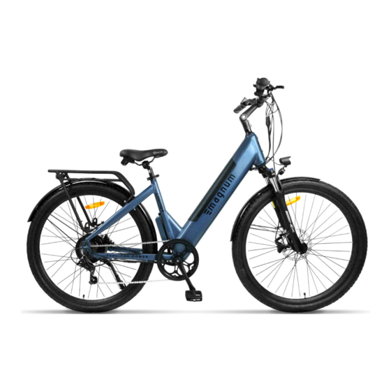
General 1.General Introduction 1.4 Bike Components 1. Rear Light 7. Rear Disc Brake 13. Kickstand 19. Adjustable Stem 2. Rear Fender 8. Saddle Handle 14. Chain 20. Front Light 3. Motor 9. Saddle 15. Pedal 21. Front Fender 4. Free Wheel 10. -
Page 5: Technical Data
1.5 Technical Data Component Cosmo X Motor 48V, 500W Bafang Rear Geared Hub Motor Battery 48V 15Ah Lithium Ion Display Magnum LCD Display Throttle Thumb Throttle Front Fork SR Suntour NEX Fork with Lockout & Preload Adjustment Crankset Brakes Clarks Hydraulic... -
Page 6: Installation And Adjustment
Installation & Adjustment 2.Installation and Adjustment 2.1 Handlebar and Stem Assembly Lift the handlebars/stem and align the stem with the head tube. Slide the stem onto the head tube and tighten the bolt at the top of the stem with a 5mm hex. -
Page 7: Assembly Of The Pedals
Installation & Adjustment 2.Installation and Adjustment 2.2 Assembly of the Pedals Identify your pedals: check the letters on the pedals, “L” or “R”. The “R” marked pedal is for the right (when facing the forward direction). For attachment to the crank, tighten clockwise. -
Page 8: Seat Position
Installation & Adjustment 2.Installation and Adjustment 2.3 Seat Position To enable comfortable, fatigue-free and safe riding, the saddle and handlebar height should be adjusted to the body size of the rider. The saddle height is correct if the leg is near full extension while the foot is resting flat on the pedal in the bottom position of the crank cycle. -
Page 9: Saddle Height
Installation & Adjustment 2.Installation and Adjustment 2.4 Saddle Height The quick-release lever must require noticeable effort to put into fully closed position to prevent any unde- sired movement while riding. WARNING An improperly closed quick release lever can open again or have limited ability to keep the saddle in place. This may cause the saddle to suddenly drop into the seat tube, potentially leading to serious falls and injury. -
Page 10: Battery And Charger
Battery & Charger 3.Battery and Charger 3.1 Overview Battery Capacity Level Light Power Button Charging Socket WARNING Please ensure that the battery is locked in place before use AC Plug¹ Charger Charging Indicator Battery Plug ¹Type will vary 3.2 General Remarks Stop charging the battery immediately if you notice anything unusual, such as smoke or a strange smell;... -
Page 11: Display
Display 4. Display 4.1 Appearance Powering ON/OFF Press and hold the power button to turn ON the display. A start-up screen (see image below) will display for approximately 2 seconds before entering the main interface showing real-time information. To turn the display OFF press and hold the power button until the screen goes blank. The display will turn off automatically if no operations are performed within the set sleep time, while the speed is 0, and current is less than 1A. - Page 12 Display 4. Display 4.2 Indicators & Buttons Walk Assist Indicator Service Tool Connection Error Code Bluetooth Battery Level Indicator Light Indicator Power Output Speed Mph Trip Information & Indicators PAS Levels Adjust Up Mode Function Adjust Down Power On Button Functions Power ON: Turns the display ON/OFF Adjust Up/Down: Changes the level of pedal assist during riding and switches functions in display settings Mode Function: Switches interface functions and enters into the display settings...
- Page 13 Display 4.Display Pedal Assist Level Short press the arrow buttons to adjust the pedal assist level up or down. There are 5 PAS levels: ECO, TOUR, SPORT, TURBO, BOOST, and BOOST+. BOOST+ is indicated by a blinking BOOST icon. When PAS level is empty it means pedal assist is off.
- Page 14 Display 4.Display Trip, Odometer, & Range Short press the M button to switch from TRIP, ODO, & RANGE on the display. The cycle order is TRIP/AVG, ODO/MAX, then RANGE/AVG. After 5 seconds with no operation preformed on the M button and the bike speed greater than 0 the display screen will switch back to the main interface.
- Page 15 Display Battery Power Battery power is shown by a battery bar indicator and percentage. The battery bar divides the power level into 5 bars. After battery capacity is lower than 5% the display enters low voltage mode. In this mode the battery level shows 0 bars.
- Page 16 Display Display Settings The following description explains how users can access the settings options in their display. Within 10 seconds of turning on the display, long press the M button to enter the settings interface. Short press the arrow buttons to switch between settings. Short press the M button to enter a specific setting.
- Page 17 Display...
- Page 18 Display Data Clearance Within 10 seconds of turning on the display, when the display shows the TRIP interface, long press the M button to show TRIP data. While the TRIP icon is blinking short press the M button to confirm data clearance. To exit long press the M button.
- Page 19 Error Code Table Each error code corresponds to a specific fault in the system. The table below is intended for the e-bike own- er to use as reference when working with Magnum Bikes technical support or a certified Magnum dealer. Error Code...
-
Page 20: Recommendations And Maintenance
Recommendations & Maintenance 5. Recommendations and Maintenance 5.1 General Requirements E-bikes use metal shells to cover the electric components, so we strongly advise against the use of exces- sive water to wash the shells and parts around them. Use a soft cloth with a neutral solution to wipe the dirt off the shells. - Page 21 Recommendations & Maintenance Maintenance Schedule Each Ride Weekly Monthly 6 Months Yearly Tire Pressure Tire Condition Visual Inspection Brake Lever Pressure Quick Releases Handlebar Alignment Saddle Alignment Battery Pack Locked Wheel Check Inspect Frame Condition¹ Clean & Lubricate Chain Check Brake Pads Lubricate Forks Lubricate Brakes &...
-
Page 22: Definition Of Tampering And Recommendations
Recommendations & Maintenance 5.3 Definition of Tampering and Recommendations Category 1 Components which can only be replaced after approval from the bicycle manufacturer/ electronic system provider Motor Controller Electric Cables Battery Sensors Display Controls Display Battery Charger Category 2 Components which can only be replaced after approval from the bicycle manufacturer Frame Hub-motor Wheel Brake Pads... -
Page 23: Warranty
Warranty 6. Warranty Your Magnum E-bike comes with a limited warranty. Please visit www.magnumbikes.com or your local Mag- num dealer for details. Bike must be registered at www.magnumbikes.com/warranty in order to be covered by the one year warranty. Stay Connected... - Page 24 E L E C T R I C B I K E S...
Need help?
Do you have a question about the Cosmo+ and is the answer not in the manual?
Questions and answers