Table of Contents
Advertisement
Quick Links
Advertisement
Table of Contents
Troubleshooting

Summary of Contents for Marport NBTE V1
- Page 1 Trawl Explorer User Guide...
-
Page 3: Table Of Contents
Contents | ii Contents Legal....................4 History...................................4 Copyright..................................5 Disclaimer..................................5 Introduction and Presentation............6 Introduction................................6 Applications.................................7 Safety Guidelines..............................8 Description.................................. 9 Firmware................................9 Technical Specifications..........................9 Main Parts..............................11 Operational Mode Indicator........................12 Installation Steps..............................13 Sensor Configuration..............14 Installing Mosa2..............................14 Connecting the Sensor to Mosa2........................15 Sounding Modes..............................18 Configuring the Uplink, Up and Down Settings.................. - Page 4 Contents | iii Installation..................41 Installing a Trawl Explorer on the Trawl..................... 41 Maintenance and Troubleshooting..........44 Interference Check..............................44 Spectrum Analyzer Display....................44 Checking Noise Interference....................45 Checking Noise Interference....................46 Charging the Sensor............................. 49 Cleaning the Sensor.............................. 50 Maintenance Checklist............................51 Troubleshooting..............................
-
Page 5: Legal
Trawl Explorer | V7 | Legal Legal History 05/09/17 First release New topics: • About Time Variable Gain on page 22 03/09/18 • Canceling the Ringing on page 25 • Frequency Plan on page 57 • New troubleshooting topic: Sensor cannot connect in wireless connection page 52 07/06/18 •... -
Page 6: Copyright
Marport. “Marport”, the Marport logo and Software Defined Sonar are registered trademarks of Marport. All other brands, products and company names mentioned are the trademark and property of its respective owners only. Marport is a division of Airmar Technology Corporation. -
Page 7: Introduction And Presentation
Tip: Click Marport logo at the bottom of pages to come back to the table of contents. Introduction Marport’s Trawl Explorer is your eye on the fishing gear. This sounder can be placed on your trawl headrope or tunnel in order to send useful information to the wheelhouse. -
Page 8: Applications
Trawl Explorer | V7 | Introduction and Presentation Applications This is an example of data received from a Trawl Explorer sensor and displayed in Scala/Scala2. Trawl Explorer display from the trawl headrope Sea bottom Fish Target strength Trawl opening... -
Page 9: Safety Guidelines
Install and use this product in accordance with this user manual. Incorrect use of the product may cause damage to the components or void the warranty. Only qualified Marport dealers can do maintenance and repairs on internal components of the sensors. -
Page 10: Description
Trawl Explorer | V7 | Introduction and Presentation Description Firmware There are three versions of the Trawl Explorer. Each version has a different firmware (called NBTE) and different features. NBTE V1 NBTE V2 NBTE V3 Name of firmware FIRM121 FIRM126... - Page 11 Warranty 2 years (Sensor & Battery)** *Reference only. Depends on functions enabled. / † Depends on sensor uplink power and options. / ‡ Based on average charging time. / **Marport Standard Marine Limited Warranty Beamwidth Beamwidths for uplink pings: Beamwidth...
-
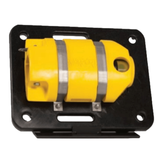
Page 12: Main Parts
Trawl Explorer | V7 | Introduction and Presentation Main Parts External View 1. Retainer screw 7. Temperature sensor 2. Model/serial 8. Positive charge number 9. Negative charge 3. Metal strap 10. Water switch 4. Transducer 11. Shoulder bolts 5. Stabilizer board 6. -
Page 13: Operational Mode Indicator
Trawl Explorer | V7 | Introduction and Presentation Operational Mode Indicator Indicators from the transducer State Situation Operation Charging Charger plug is Batteries are charging. No light. connected. Running Sensor is in water or After an initialization phase, activated with jumper. echo sounder is operating. -
Page 14: Installation Steps
Trawl Explorer | V7 | Introduction and Presentation Installation Steps Click an installation step to jump directly to the corresponding section. Note: You can customize the display of data on Scala/Scala2 at any time. | 13... -
Page 15: Sensor Configuration
Important: If the computer is under OS X Mavericks, Yosemite or El Capitan, use Mosa2 version 02.03. Procedure 1. Double-click the *.dmg file received from Marport. 2. From the installation window that appears, drag Mosa2 icon to Applications. Mosa2 is added to the Launchpad 3. -
Page 16: Connecting The Sensor To Mosa2
Click the magnifying glass from the top right corner of your screen and type Terminal. b) Select Terminal from the results. c) In the terminal, enter sh /Volumes/Marport-Mosa2/MosaPatchForMavericks.sh d) When prompted, enter the administrator password. e) Close the terminal. - Page 17 Trawl Explorer | V7 | Sensor Configuration Procedure 1. To connect the sensor using a wireless communication: a) Connect the water-switch. The LED flashes red. b) Disconnect the water-switch. After a few seconds, the LED flashes green. c) Open Mosa2, then wait a few seconds for the sensor to be recognized. When it appears on the discovery page, click 2.
- Page 18 Trawl Explorer | V7 | Sensor Configuration Note: You can keep the Configuration Cable continuously connected by USB, and virtually eject or connect it when Mosa2 is in discovery mode. Click Menu > Eject Config Plug or Connect Config Plug. If ejected, the cable stays disconnected until you virtually connect to it or manually disconnect then connect it.
-
Page 19: Sounding Modes
Trawl Explorer | V7 | Sensor Configuration Sounding Modes The sensor can send pings according to three different sounding modes. Down 1 Sensor sends pings towards down direction (1) only. You can see fish going into the trawl. Pings are sent quicker than with the other modes, so more data is received, which enables a better horizontal resolution. -
Page 20: Configuring The Uplink, Up And Down Settings
Trawl Explorer | V7 | Sensor Configuration Configuring the Uplink, Up and Down Settings You can configure different settings for uplink, down and up soundings. Before you begin The sensor is connected to Mosa2. About this task Remember: Always click Apply after you change a setting and make sure there is a green check mark Procedure Click the tab Trawl Explorer. - Page 21 Trawl Explorer | V7 | Sensor Configuration Important: Down 1 + Down 2 sounding mode: configure Down 1 sounding in Down settings and Down 2 sounding in Up settings (Up Sounding Range, Ping Up Length, Ping Up Frequency, Up channel minimum TS, Up TVG Mode, TVG Up). 2.
-
Page 22: Target Strength
Important: Frequency needs to be between 120-210 kHz. Important: Do not change ping frequency on a V3 sensor or it will have to be returned to a Marport sales' office for target strength calibration. Target Strength Procedure For V3 version of sensors, Down channel minimum TS and Up channel minimum TS helps you detecting targets on the echogram. -
Page 23: About Time Variable Gain
Trawl Explorer | V7 | Sensor Configuration • 20 log: focus on bottom or school of fish. • 40 log: focus on individual targets. • 30 log: compromise between the two above settings. For V1 and V2 versions of sensors, go to TVG Down and, if applicable, TVG Up: •... -
Page 24: Configuring Measurement Sending Sequence And True Mode
Trawl Explorer | V7 | Sensor Configuration Configuring Measurement Sending Sequence and True Mode If you use the True Mode display for echograms in Scala/Scala2, you need to select a specific sequence of measurements (e.g. temperature, pitch, roll...) sent by the uplink to the receiver. Before you begin The sensor is connected to Mosa2. -
Page 25: Selecting A1 Board Orientation
Trawl Explorer | V7 | Sensor Configuration Selecting A1 Board Orientation You need to check the orientation of the A1 board inside the sensor in order to correctly receive data. Before you begin The sensor is connected to Mosa2. CAUTION: Do not open the sensor to check the A1 board orientation. It can be checked and configured using Mosa2. -
Page 26: Canceling The Ringing
Trawl Explorer | V7 | Sensor Configuration 1. Vertical 2. Standard (horizontal) Canceling the Ringing On NBTE V2 echograms, there is a ringing coming from the transducer, that appears as a red line on top of the echogram. You can cancel it. Before you begin •... - Page 27 Trawl Explorer | V7 | Sensor Configuration The sensor emits 10 pings and you can see a curve on the graph. 4. Select Adjust profile points on top of the graph. 5. From the graph, click and drag red line points above the gray and yellow curves: a) The red line should follow the same curve.
- Page 28 Trawl Explorer | V7 | Sensor Configuration Note: The values below the red line will not appear on the echogram and data above will appear as a red line on the echogram. 6. Click Apply and make sure there is a green check mark 7.
-
Page 29: Configuring The Uplink Power
Trawl Explorer | V7 | Sensor Configuration Configuring the Uplink Power You can increase the uplink power of the sensor to increase the power of the signal transmitted. It is useful if you have interferences or if the sensor is far from the vessel. Before you begin The sensor is connected to Mosa2. -
Page 30: Exporting Sensor Configuration Settings For Record Keeping
Trawl Explorer | V7 | Sensor Configuration 4. Check the following measures: • The temperature is consistent with the sensor environment. • The depth is between 0 and 2m. • The battery is between 6.9V and 8.1V. Troubleshooting: If depth is incorrect, you can put an offset in Depth > Depth Offset. The other measures are only useful for the support service. -
Page 31: Exporting Sensor Configuration Settings For The Receiver
Trawl Explorer | V7 | Sensor Configuration The settings are displayed. 4. To save the settings: • Click Save to file to download the file on the computer. • Or, click Copy to clipboard, then press Cmd + V on a word processor like Pages to paste the contents. - Page 32 Trawl Explorer | V7 | Sensor Configuration • Click Save to file to download the XML file on the computer. • Or, click Copy to clipboard, then press Cmd + V on a word processor like Pages to paste the contents.
-
Page 33: System Configuration And Display
You need to add the Trawl Explorer to the receiver in order to display sensor data on Scala/Scala2. About this task The Trawl Explorer is compatible with the following M3/M4/M5/M6 receiver and Scala versions: Mx version Scala/Scala2 version NBTE V1 (FIRM121) NBTE V2 (FIRM126) 03.01.23 or later NBTE V3 (FIRM128) 04.02.28 or later 01.02.05 or later... - Page 34 Trawl Explorer | V7 | System Configuration and Display 3. Click the tab Add from Marport Sensor Config Utility. 4. Click Browse and select the XML file. Information about the sensor is displayed. 5. Select a node from the list on the left. Nodes in green are already used.
-
Page 35: Adding The Sensor Manually
Trawl Explorer | V7 | System Configuration and Display Results You can see incoming data in the control panels, in Sensors Data/ What to do next • If you want to apply filters on data received by the sensor, see Configuring the Sensor Settings on page 35. -
Page 36: Configuring The Sensor Settings
Trawl Explorer | V7 | System Configuration and Display 8. Click Add Sensor. The sensor is added to the receiver and displayed on the left side of the page. The configuration page is displayed. Configuring the Sensor Settings Important: Make sure the settings you enter here are the same as in Mosa2. | 35... - Page 37 Trawl Explorer | V7 | System Configuration and Display Sensor name displayed in Scala/Scala2 and its features. This setting helps detecting the signal of the sensor among other sensor or echosounder signals. Change default setting only if you have issues receiving data. •...
-
Page 38: Configuring The Sensor Display On Scala/Scala2
Trawl Explorer | V7 | System Configuration and Display Select the range of Down sounding from the drop-down menu. Select Up-Sounding if the sounding mode of the sensor is Down 1 + Up. Then, select the range of Up sounding. Select Double Down if the sounding mode is Down 1 + Down 2. - Page 39 Trawl Explorer | V7 | System Configuration and Display Procedure 1. From the top left corner of the screen, click Menu > Customize and enter the password eureka. 2. To display the echogram view: a) Open the control panels, then go to Sensors Data / b) In Trawl Explorer, click and hold Range of Sonar Data for 3 seconds until a rectangle appears and drag it to a page.
- Page 40 Trawl Explorer | V7 | System Configuration and Display becomes lower than 20 meters (1). This way, the echogram displays better quality images when the distance to the bottom is shorter. Echogram images will be displayed like the example below: You can see that the range of the sounding adapts to the bottom detected.
- Page 41 Trawl Explorer | V7 | System Configuration and Display 7. Deactivate the Customize mode when you have finished customizing pages: click Menu > Customize again. | 40...
-
Page 42: Installation
Trawl Explorer | V7 | Installation Installation Learn how to install Trawl Explorer sensors on the trawl gear. Installing a Trawl Explorer on the Trawl We recommend to install the sensor on the headrope in order to see the trawl opening and fish entering the trawl. - Page 43 Trawl Explorer | V7 | Installation 1. Place sensor (1) at the centre of the net's headrope (2), facing the vessel. 2. Install a double-mesh piece of netting (3) to stabilize the sensor. 3. Buoys (4) on either sides provide a level platform for the unit during trawling operations. 4.
- Page 44 Trawl Explorer | V7 | Installation The installation procedure is the same as the one for the headrope. | 43...
-
Page 45: Maintenance And Troubleshooting
Trawl Explorer | V7 | Maintenance and Troubleshooting Maintenance and Troubleshooting Read this section for troubleshooting and maintenance information. Interference Check You can check if there is noise interfering with the reception of signals. Spectrum Analyzer Display The following picture explains the main parts of the spectrum analyzer page on Scala/Scala2. Start/Stop spectrum 10 Marker: display frequency and levels of noise (dB) analyzer... -
Page 46: Checking Noise Interference
Trawl Explorer | V7 | Maintenance and Troubleshooting Checking Noise Interference You can use the spectrum analyzer to check the noise level of the hydrophones and check for interference. About this task Spectrum Analyzer Display on page 44 for details about the spectrum analyzer display. Procedure 1. -
Page 47: Checking Noise Interference
Trawl Explorer | V7 | Maintenance and Troubleshooting 6. To see the maximum, mean and real time measures of noise level at a specific frequency, select Marker on the left side of the screen and move the mouse over the graph. Frequency and levels of noise (dB) at the mouse pointer location are displayed under Marker. - Page 48 Trawl Explorer | V7 | Maintenance and Troubleshooting 5. The spectrum analyzer is displayed. You can display up to 6 spectrum analyzers at the same time. Below is an example of a page with two spectrum analyzers. The FFT plot shows three levels of noise in dBV: 1.
- Page 49 Trawl Explorer | V7 | Maintenance and Troubleshooting • RealTime: the latest highest level of noise (dBV) recorded and its frequency. • Max: the highest level of noise recorded since the beginning of the spectrum and its frequency. 8. Check that there is more than 12 dBV between the maximum noise level (dark blue line) and the average noise level (cyan line) on the peak of sensor frequencies.
-
Page 50: Charging The Sensor
14. Right-click the IP address of the receiver in the status bar and click Stop Spectrum. Charging the Sensor Charge the sensor at any battery level with either Marport Basic Sensor Charger or Marport Medusa II Multi-charger. About this task The sensor uses lithium-ion batteries. -
Page 51: Cleaning The Sensor
Trawl Explorer | V7 | Maintenance and Troubleshooting 6. Plug in the charger to a 110-240 V AC 50-60 Hz socket. 7. If you have the multi-charger, turn the power switch to the ON position. The power switch lights on. If not, check the AC power cord connection. 8. -
Page 52: Maintenance Checklist
Every 2 years The sensor must be returned to an approved Marport dealer for inspection and maintenance. If the sensor has not been not used for more than 3 months, we highly recommend to check the following points before using it: •... -
Page 53: Troubleshooting
Trawl Explorer | V7 | Maintenance and Troubleshooting Troubleshooting Read this section to know how to solve common problems. Mosa2 does not open due to error message Mosa2 displays an error message saying it cannot be opened. Your Mac security preferences do not allow you to open applications not downloaded from the App Store. -
Page 54: Sensor Does Not Connect Correctly With Mosa2 When Using The Configuration Cable
• Make sure the three pins are fully inserted inside the sensor. Mosa2 does not automatically open when connecting the Configuration Cable. • Check that you see Marport Captain icon in the desktop taskbar. If you do not see it: close, then open Mosa2. The icon should appear in the taskbar. -
Page 55: Data In Scala/Scala2 Is Wrong
• Disconnect both USB connector and three-pin plug. Then, connect again the Configuration Cable. If the message is still displayed, it means there is an issue with the sensor’s components. Contact Marport support. Data in Scala/Scala2 is wrong Data displayed in Scala/Scala2 is wrong and the echogram is noisy. -
Page 56: Pitch And Roll Are Wrong
Trawl Explorer | V7 | Maintenance and Troubleshooting 2. If not, change the frequency. You may have dragged and dropped wrong sonar data to the display. 1. Check that the name of the sensor on the top left corner of the echogram is Trawl Explorer. 2. -
Page 57: Support Contact
Trawl Explorer | V7 | Maintenance and Troubleshooting Support Contact You can contact your local dealer if you need maintenance on your Marport products. You can also ask us at the following contact details: FRANCE ICELAND Marport France SAS Marport EHF 8, rue Maurice Le Léon... -
Page 58: Appendix
Trawl Explorer | V7 | Appendix Appendix Frequency Plan It is important to carefully plan the setup of your sensors before adding them to the system. You can create a table with a list of frequencies and complete it when you add sensors. Boat &... - Page 59 Trawl Explorer | V7 | Appendix C-4/CH5 42700 C-4/CH6 43300 C-5/CH1 42024 C-5/CH2 41690 C-5/CH3 41285 C-5/CH4 41060 C-5/CH5 42900 C-5/CH6 43400 C-6/CH1 39062 C-6/CH2 39375 C-6/CH3 39688 C-6/CH4 40000 C-6/CH5 40312 C-6/CH6 40625 C-7/CH1 38906 C-7/CH2 39219 C-7/CH3 39531 C-7/CH4 39844 C-7/CH5...
- Page 60 Trawl Explorer | V7 | Appendix Frequencies and intervals The diagrams below show the bandwidth of the different types of Marport sensors and intervals you must respect when adding other sensors. Figure 2: PRP sensors (e.g. Catch sensor, Trawl Speed, Spread sensor...) Example: If the frequency of the sensor is 40kHz, there should be no sensors between 39.9-40kHz...
- Page 61 Trawl Explorer | V7 | Appendix Examples of frequency allocations • We recommend to allocate frequencies between 34 and 56 kHz for wideband hydrophones and between 41 kHz and 44 kHz for narrowband hydrophones. • Echosounders are usually placed around 38 kHz, make sure to allow enough distance with them. | 60...
- Page 62 Trawl Explorer | V7 | Appendix | 61...
-
Page 63: Index
Index | 62 Index Frequency plan Battery life Beamwidth Indicators Boat code Installation Installation steps Channel code Charger Maintenance LEDs Plugging Cleaning Compatibility Maintenance Mosa Schedule Operating System Measurement sending sequences Config Read Measures Configuration Cable Mosa Connecting Allow apps downloaded from Contact Bad connection Cannot connect wireless... - Page 64 Index | 63 Receiver Adding sensor Compatible versions Configuration file Sensor options Web page Ringing cancellation Scala Adding sensor Configuring sensor Displaying in Filters Trawl gear location Select orientation Sensor location Sounding Double Down Down Settings Spectrum System requirements Target strength Technical specifications Transducer orientation Selecting...
Need help?
Do you have a question about the NBTE V1 and is the answer not in the manual?
Questions and answers