Table of Contents
Advertisement
Quick Links
Advertisement
Table of Contents

Related Manuals for Weidmüller EM122-RTU-2P


Summary of Contents for Weidmüller EM122-RTU-2P
- Page 1 EM122-RTU-2P Manual...
- Page 2 Revision History Version Date Change 2021.3.9 First edition...
-
Page 3: Table Of Contents
Contents General ........................................5 Copyright ..................................... 5 Trademarks ....................................5 Disclaimer ....................................5 Meaning of the symbols ................................. 5 Application notes ..................................6 About these operating instructions ............................ 7 Incoming goods inspection ................................8 Scope of delivery ..................................8 Product description ................................... 9 Intended use .................................... - Page 4 Number Entry Procedure ............................29 Change Password ................................30 DIT Demand Integration Time ............................31 Backlit Set-up ................................... 32 Supply System ..................................33 Pulse Output ..................................... 34 Pulse Rate ....................................35 Pulse Duration ..................................36 Communication ..................................37 RS485 Address ................................37 Baud Rate ..................................
-
Page 5: General
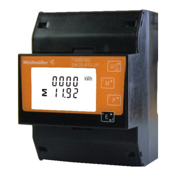
General This manual applies to the products: 7760051003 Energy Meter EM122-RTU-2P Copyright This manual is subject to the laws of copyright protection and may not be mechanically or electronically photocopied, reprinted, reproduced or otherwise reproduced or published in part or as a whole, without the legally binding, written consent of Weidmüller Interface GmbH &... -
Page 6: Application Notes
Application notes Please read these operating instructions and all other publications that must be consulted in order to work with this product (particularly for installation, operation or maintenance). Please observe all safety regulations and warnings. Non-compliance with the instructions can lead to personal injury and/or damage to the product. -
Page 7: About These Operating Instructions
Only screw terminals with the same Safety is no longer guaranteed and the device may be dangerous if the device number of poles and the same type may is not operated according to the be plugged together. operating instructions. All signals connected with the Conductors consisting of single wires device’s SELV circuit must also must be provided with ferrules. -
Page 8: Incoming Goods Inspection
Incoming goods inspection The proper and safe operation of this device requires appropriate transport, proper storage, installation and assembly as well as careful operation and maintenance. When it is assumed that safe operation is no longer possible, the device must immediately be taken out of operation and secured against accidental start-up. -
Page 9: Product Description
Measurement voltages and measurement currents must originate from the same grid. Energy Meter EM122-RTU-2P supports max. 100A direct connection, saves the cost and avoid the trouble to connect external CTs, giving the unit a cost-effective and easy operation. -
Page 10: Specifications
Specifications Electrical characteristics Type of measurement RMS including harmonics on three phase AC system (3P, 3P+N) Measurement Voltage 0.5% accuracy Current 0.5% Frequency 0.2% Power Factor ±0.01 Active Power Reactive Power Apparent Power Active Energy IEC62053-21 Class 1 Reactive Energy Input-Voltage 230 V L-N 80%-120% of Un... - Page 11 Digital output Pulse output 1 0.001/0.01/0.1/1kWh/kVarh(configurable) Pulse output 2 400imp/kWh(non-configurable) Mechanical Characteristics Weight 350g IP51 for front display; IP Degree of Protection (IEC 60529) IP20 for others Dimensions (WxHxD) 72x100x66mm Material of meter case UL 94-V0 Environmental Characteristics Operating Temperature -25 ~ 55°C Storage Temperature -40 ~ 70°C...
-
Page 12: Operating Concept
Transmission speed 2400bps~38400bps Parity None (default), Odd, Even Stop bits 1 or 2 Connection capacity of the terminals(voltage measurement) Single-wire, multi-wire, finely stranded condu- 2.5-25mm ctor Pin terminals,ferrules 2.5-25mm Tightening torque 2-3 Nm Stripping length 15mm Connection capacity of the terminals(RS485 and output) Single-wire, multi-wire, finely stranded condu- 0.5-1.5mm ctor... -
Page 13: Em Configuration Tools
EM configuration tools The Energy Meter 122 can be programmed and read with the EM configuration tools software. For this, a PC must be connected to the RS485 interface of the Energy Meter 122 via an RS485 Modbus to TCP/IP gateway. Connection options Connection of Energy Meter 122 to PC via an EM220-RTU-4DI2DO-GW as a gateway: - 13... -
Page 14: Assembly
Assembly Installation location The Energy Meter 122 can be installed in control cabinets or in small distribution boards according to DIN 43880. It is mounted on a 35 mm mounting rail according to DIN EN 60715. It can be installed in any position. DIN Rail Fig.: Energy Meter 122 on mounting rail according to DIN EN 60715 Power supply... -
Page 15: Voltage And Current Measurement Inputs
Voltage and current measurement inputs When connecting the voltage and current measurement, the following must be observed: Isolation device A suitable circuit breaker must be fitted to disconnect and deenergize the Energy Meter 122. • The circuit breaker must be placed in the vicinity of the Energy Meter 122, be marked for the user and •... -
Page 16: Direction Of The Current
Attention! The voltage and current should not exceed the allowable range. Attention! The Energy Meter 122 is not suitable for the measurement of DC voltages. Attention! The voltage measurement inputs on the Energy Meter 122 are dangerous to touch! The attached screw terminal has to be fixed sufficiently with the screws on the device! Direction of the current Please wire in strict accordance with the current direction. -
Page 17: Terminating Resistors
Terminating resistors The cable should be terminated with resistors (120 ohm 1/4 W) at the beginning and end of a segment if the communication distance larger than 300m. The Energy Meter 122 has no terminating resistors. Shielding A twisted and shielded cable must be provided for connections via the RS485 interface. Ground the shields of all cables that run into the cabinet at the cabinet entry. -
Page 18: Cable Type
Fig.: Shielding design for cabinet entry Cable type The cable used must be suitable for an ambient temperature of at least 80 °C. For the wiring of the Modbus connection, CAT cables are not suitable. Please use the recommended cables. Maximum cable length Max 1000m. - Page 19 - 19...
-
Page 20: Pulse Output
Pulse Output The meter is equipped with 2 pulse outputs, which are fully isolated from the inside circuit: •That generates pulses in proportion to the measured energy. •The digital outputs are not short circuit protected. •An external auxiliary voltage with overcurrent protective device is required, voltage range is 5-27VDC. -
Page 21: Examples Of Electrical Connections
Examples of electrical connections 7760051003 7760051003 EM122-RTU-2P U / I EM122-RTU-2P U / I 1P2W 3P3W L1 L2 L3 7760051003 EM122-RTU-2P U / I L1 L2 L3 RS485 / DO 3P4W - 21... -
Page 22: Configuration And Display
Configuration and display Self-check after power on When device is power on, the meter will initialize and do self-check: Full screen Self-check passed Software version It will last for 3s The software version is different according to the actual situation. After a short delay, the screen will display active energy measurements. -
Page 23: Button Functions
Button functions Buttons Click Press 2S ➢ Selects the Voltage and Current display screens ➢ In Set-up Mode, this is the “Left” or “Back” button ➢Select the Frequency and Power factor display screen ➢ In Set-up Mode, this is the “Up” button ➢... -
Page 24: Overview Of Measured Value Displays
Overview of measured value displays Voltage and Current Each successive pressing of the button selects a new range: Phase to neutral voltages(3p4w) Phase to neutral voltages(3p3w) Current on each phase Phase to neutral voltage THD%(3p4w) Phase to neutral voltage THD%(3p3w) - 24... -
Page 25: Frequency And Power Factor And Demand
Current THD% for each phase Frequency and Power Factor and Demand Each successive pressing of the button selects a new range: Frequency and Power Factor (total) Power Factor of each phase Maximum Power Demand Maximum Current Demand - 25... -
Page 26: Power
Power Each successive pressing of the button select a new range: Instantaneous Active Power in kW Instantaneous Reactive Power in kVAr Instantaneous Volt-amps in KVA Total kW, kVArh, kVA - 26... -
Page 27: Energy Measurement
Energy Measurement Each successive pressing of the button selects a new range: Imported active energy in kWh Exported active energy in kWh Imported reactive energy in kVArh Exported reactive energy in kVArh Total active energy in kWh Total reactive energy in kVArh - 27... -
Page 28: Configuration Menu
Configuration menu Set-up Mode To enter set-up mode, pressing the button for 3 seconds, until the password screen appears. Setting up is password-protected so you must enter the correct password (default ‘1000’) before processing. If an incorrect password is entered, the display will show: Err To exit setting-up mode, press repeatedly until the measurement screen is restored. -
Page 29: Set-Up Entry Methods
Set-up Entry Methods Some menu items, such as password, require a four-digit number entry while others, such as supply system, require selection from a number of menu options. Menu Option Selection Use the buttons to select the required item from the menu. Selection does not roll over between bottom and top of list. -
Page 30: Change Password
Change Password Use the to choose the change password option. Press the to enter the change password routine. The new password screen will appear with the first digit flashing. to set the first digit and press to confirm your selection. The next digit will flash. -
Page 31: Dit Demand Integration Time
DIT Demand Integration Time This sets the period in minutes over which the current and power readings are integrated for maximum demand measurement. The options are: 0, 5, 8, 10, 15, 20, 30, 60 minutes. From the set-up menu, use buttons to select the DIT option. -
Page 32: Backlit Set-Up
Backlit Set-up The backlit lasting time is settable Default lasting time is 60minutes For example, if it’s set as 5, the backlit will be off in 5minutes from the last time operation on the meter. Press to enter the selection routine. The current time interval will flash The options can be: 0(always on),5,10,30,60,120minutes. -
Page 33: Supply System
Supply System Use this section to set the type of power supply being monitored. From the Set-up menu, use buttons to select the system option. The screen will show the currently selected power supply. Press to enter the selection routine. The current selection will flash. -
Page 34: Pulse Output
Pulse Output This option allows you to configure the pulse output 1. The output can be set to provide a pulse for a defined amount of energy active or reactive. Use this section to set up the pulse output for: Total kWh/ Total kVArh Import kWh/Export kWh Import KVArh/Export KVArh... -
Page 35: Pulse Rate
Pulse Rate Use this to set the energy represented by each pulse. Rate can be set to 1 pulse per dFt/0.01/0.1/1/10/100kWh/kVArh. (It shows 1 impulse = 10kWh/kVArh) From the Set-up menu, use buttons to select the pulse rate option. Press to enter the selection routine. -
Page 36: Pulse Duration
Pulse Duration The energy monitored can be active or reactive and the pulse width can be selected as 200, 100(default) or 60ms. (It shows pulse width of 200ms) From the Set-up menu, use buttons to select the pulse width option. Press to enter the selection routine. -
Page 37: Communication
Communication There is a RS485 port can be used for communication using Modbus RTU protocol. For Modbus RTU, parameters are selected from Front panel. RS485 Address (It shows pulse width of 200ms). From the Set-up menu, use buttons to select the Address ID. Press to enter the selection routine. -
Page 38: Baud Rate
Baud Rate From the Set-up menu, use buttons to select the baud rate option. Press to enter the selection routine. The current setting will flash. buttons to choose baud rate 2.4k. 4.8k, 9.6k, 19.2k, 38.4k. On completion of the entry procedure, press to confirm the setting and press to return to the main set up menu. -
Page 39: Parity
Parity From the Set-up menu, use buttons to select the parity option. Press to enter the selection routine. The current setting will flash. buttons to choose Parity (EVEN / ODD / NONE). On Completion of the entry procedure, press to confirm the setting and press to return to the main set up menu. -
Page 40: Stop Bits
Stop Bits From the Set-up menu, use buttons to select the stop bit option. Press to enter the selection routine. The current setting will flash. buttons to choose Stop Bit (2 or 1). On Completion of the entry procedure, press to confirm the setting and press to return to the main set up menu. -
Page 41: Clr
The meter provides a function to reset the maximum demand value of current and power. From the Set-up menu, use buttons to select the reset option. Press to enter the selection routine. The MD will flash. Press to confirm the setting and press to return to the main set up menu. -
Page 42: Modbus Communication Protocol
Modbus Communication Protocol Input Registers, Function code 04 Modbus Protocol Start Address Hex Input Register Parameter Length Address Data (Byte) (Register) Description Units Format Byte Byte 30001 Phase 1 line to neutral volts Float 30003 Phase 2 line to neutral volts Float 30005 Phase 3 line to neutral volts... - Page 43 30081 Total apparent energy Float kVAh 30083 Float 30085 Total system power demand Float Maximum total system power demand 30087 Float 30101 Total system VA demand Float 30103 Maximum total system VA demand Float 30105 Neutral current demand Float Amps 30107 Maximum neutral current demand Float...
- Page 44 30375 L3 export reactive energy Float kVArh 30377 L1 total reactive energy Float kVArh 30379 L2 total reactive energy Float kVArh 30381 L3 total reactive energy Float kVArh Notes: The power factor has its sign adjusted to indicate the direction of the current. Positive refers to forward current, negative refers to reverse current.
-
Page 45: Holding Register, Function Code 03/10
Holding Register, Function code 03/10 Modbus Protocol Address Parameter Start Address Hex Parameter Valid Range Mode Register Number Hi Byte Lo Byte Read minutes into first demand calculation. When the demand time reaches the demand Demand 40001 Period then the demand values are valid. Time Length: 4 bytes Data Format: Float... - Page 46 Write the network port node address: 1 to 247 for MODBUS Protocol, default 1. Requires a Modbus 40021 restart to become effective. Address Length: 4 bytes Data Format: Float Write pulse divisor index: n = 0 to 5 0-0.0025 kWh(kVArh)/imp 1-0.01 kWh(kVArh)/imp 2-0.1 kWh(kVArh)/imp Pulse1...
- Page 47 Write MODBUS Protocol input para-meter for Pulse 1 pulse out 1:37 = total kWh or 39 = total kVarh, 40087 Energy default 39. Type Length: 4 bytes Data Format: Float 0000: reset the Maximum demand 0003: reset the resettable energy 461457 30729 Reset...
-
Page 48: Dimensional Drawings
Dimensional drawings All dimensions in mm. Front view Side view Voltage input RS485 Pulse output 7760051003 EM122-RTU-2P Voltage output Connecting example A G - + - + Signal Input Output 3P3W 3P4W 1P2W 3P3W 3P4W 1P2W Fig.: Connecting example The overcurrent protection device must be UL/IEC certified.
Need help?
Do you have a question about the EM122-RTU-2P and is the answer not in the manual?
Questions and answers