Table of Contents
Advertisement
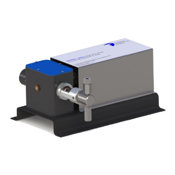
INTRODUCTION
The model 4000 Chemical Injection Pump is designed to inject low to medium volumes of chemical into high pressure lines. Depending on
the motor and plunger configuration, these pumps are capable of pumping against up to 6000 PSI or up to 130 gallons/day. Due to the
varying nature of applications, proper sizing is essential for each solar powered application to ensure pump performance. Timberline
Manufacturing and it's associated representatives are available to assist with any questions or pump sizing. Variables you will need to know
to ensure proper sizing are:
Required Flow Rate
Discharge Pressure
Location of Pump
Mission Critical Level of Application
These systems are typically sold including a pump unit, solar panels, solar panel mounting hardware and pipe, solar power voltage
regulator, pump controller, and battery/controller enclosure. Batteries are generally supplied by the end user after a sizing
recommendation by Timberline Manufacturing or their associated representatives, but are available upon request.
TABLE OF CONTENTS
SECTION
1
Solar Powered Chemical Injection Pump
Installation, Operation, and Maintenance Instructions
Series 4000
PAGE
2
2
2
2
3
4
6
6
7
8
9
10
10
10
11
12
13
14
15
16
16
16
18
19
20
Advertisement
Table of Contents

Summary of Contents for Timberline 4000 Series
-
Page 1: Table Of Contents
6000 PSI or up to 130 gallons/day. Due to the varying nature of applications, proper sizing is essential for each solar powered application to ensure pump performance. Timberline Manufacturing and it’s associated representatives are available to assist with any questions or pump sizing. -
Page 2: Important Safety Precautions
Main Office 11122 West Little York RD Houston, TX 77041 713-466-3552 Norrisealwellmark.com IMPORTANT SAFETY PRECAUTIONS Read this manual completely and carefully. Pay special attention to all warnings, cautions, and safety rules. Failure to follow the instructions could produce safety hazards which could injure personnel or damage the pump or motor. If you have any doubts about how to connect the pump or motor, refer to the pertaining sections of this manual. -
Page 3: Pressure And Flow Rate Information
SHOULD BE DONE AFTER READING THIS MANUAL AND ALL APPLICABLE SAFETY STANDARDS. IF IN DOUBT, CONTACT YOUR Caution LOCAL TIMBERLINE MANUFACTURING REPRESENTATIVE OR THE HOME OFFICE. DETERMINATION OF SYSTEM FITNESS FOR PURPOSE OR USE IS SOLELY THE CUSTOMER’S RESPONSIBILITY. *Advertised minimum and maximum flow rates shown were tested at 0 PSI; increased discharge pressure may result in increased minimum and reduced... -
Page 4: Maximum Flow Rate Curves
Main Office 11122 West Little York RD Houston, TX 77041 713-466-3552 Norrisealwellmark.com MAXIMUM FLOW RATE CURVES: 4000 MOTOR ON/OFF CONTROLLER 1/4" Plunger 3/16" Plunger 1/4" Dual 3/16" Dual 1/4" Single 3/16" Single 1000 2000 3000 4000 5000 6000 1000 2000 3000 4000 5000... - Page 5 MAXIMUM FLOW RATE CURVES: 4001 MOTOR ON/OFF CONTROLLER 1/4" Plunger 3/16" Plunger 1/4" Dual 3/16" Dual 1/4" Single 3/16" Single 1000 1500 2000 2500 1000 2000 3000 4000 5000 3/8" Plunger 1/2" Plunger 3/8" Dual 1/2" Dual 1/2" Single 3/8" Single 1000 1250 CONTINUOUS RUN CONTROLLER...
-
Page 6: Solar Pump Assembly
Main Office 11122 West Little York RD Houston, TX 77041 713-466-3552 Norrisealwellmark.com SOLAR PUMP ASSEMBLY PUMP ASSEMBLY BODY ASSEMBLY SHOWN ON PAGE 8 *Single Head configuration shown... -
Page 7: Pump Assembly Parts List
SOLAR PUMP ASSEMBLY PUMP ASSEMBLY PARTS LIST QUANTITY SINGLE DUAL PART ITEM NUMBER DESCRIPTION MATERIAL HEAD HEAD 75260 BASE PLATE CARBON STEEL 70022 MOTOR 1/5 HP, BRUSHLESS 75360 HEX SCREW 1/4-20 X .625 CARBON STEEL 75320 COUPLING .625 BORE ALUMINUM 75321 COUPLING .50 BORE ALUMINUM... -
Page 8: Body Assembly And Parts List
Main Office 11122 West Little York RD Houston, TX 77041 713-466-3552 Norrisealwellmark.com SOLAR PUMP ASSEMBLY BODY ASSEMBLY AND PARTS LIST QUANTITY SINGLE DUAL ITEM PART NUMBER DESCRIPTION MATERIAL HEAD HEAD 75180 PACKING NUT, 3/16" 75181 PACKING NUT, 1/4" 303 SST 75182 PACKING NUT, 3/8"... -
Page 9: Included Components
INCLUDED COMPONENTS Components below are shown for a standard, single panel solar pump setup (e.g. part number 4000-4A1A-02). Additional panels, battery enclosures, and charge controllers are available for systems requiring additional power. Your product is delivered with the following components: ITEM DESCRIPTION Pump Unit... -
Page 10: Installation
PERFORMED. THIS SHOULD BE DONE AFTER READING THIS MANUAL AND ALL APPLICABLE SAFETY STANDARDS. Caution IF IN DOUBT, CONTACT YOUR LOCAL TIMBERLINE MANUFACTURING REPRESENTATIVE OR THE HOME OFFICE. DETERMINATION OF SYSTEM FITNESS FOR PURPOSE OR USE IS SOLELY THE CUSTOMER’S RESPONSIBILITY. -
Page 11: Tubing Schematic
INSTALLATION TUBING SCHEMATIC... -
Page 12: Solar Panel Mounting And Assembly
HEALTH ACT (OSHA) SHOULD BE OBSERVED TO REDUCE HAZARDS TO PERSONNEL AND PROPERTY. Warning TIMBERLINE MANUFACTURING PROVIDES A SUPPLIED WIRING HARNESS FOR DC POWER CONNECTIONS UTILIZING TYPE B LIQUIDTIGHT FLEXIBLE NONMETALLIC CONDUIT AND APPLICABLE FITTINGS. DETERMINATION OF SYSTEM FITNESS FOR PURPOSE OR USE IS SOLELY THE CUSTOMER’S RESPONSIBILITY. -
Page 13: Solar Panel Positioning
INSTALLATION SOLAR PANEL POSITIONING The solar panel should be positioned to achieve maximum solar exposure. Proper adjustment of the mounting assembly is critical to proper performance of the assembly. Rotation: Loosen the rotation set screw on the adjustment tee (shown below) and position the panel so that it is facing true south (for northern hemisphere installations) or true north (for southern hemisphere installations), then re-tighten the set screw. -
Page 14: Wiring
Main Office 11122 West Little York RD Houston, TX 77041 713-466-3552 Norrisealwellmark.com INSTALLATION WIRING Insert batteries into the battery/control enclosure and ensure that batteries are wired in parallel using the provided battery jumper cables. An example of parallel wiring is shown below. Locate the positive (red) and negative (black) battery wires which are pre wired into the controller and ASC. -
Page 15: Wiring Diagrams
INSTALLATION WIRING DIAGRAMS Continuous Run, Variable Speed Controller On/Off Controller *For any additional or more detailed information contact the manufacturer. -
Page 16: Operation
Timberline Mfg. Company 3255 Executive Blvd. Suite 108 Beaumont, Tx 77705 MAINTENANCE PUMP Lubricate shaft and bearings with multi purpose grease. Alternatively, lubricate by filling the pump housing with hydraulic oil. Add or replace lubricant quarterly, as a minimum. Use lubricant suitable for climate where the pump is installed. -
Page 17: Troubleshooting
TROUBLESHOOTING SYMPTOM PROBABLE CAUSE VERIFICATION CORRECTIVE ACTION Low battery voltage Voltage test battery See other section Replace fuse (Proper diagnosis should Fuse blown Fuse visibly blown be performed to determine cause of fuse failure) Verify all valves between injection point Pump operates when bleed screw is Obstructed flow and pump are open and lines are free... -
Page 18: Ordering Information
Before setting up any solar pump system, contact the manufacturer for proper sizing based on your location, pressure, and flow rate. Improper sizing and/or unintended use may cause system failure. While this information is presented in good faith and believed to be accurate, Timberline Manu- facturing Company does not guarantee results based upon such information. Timberline Manu- facturing Company reserves the right to change the design or specifications of these products without notice.
Need help?
Do you have a question about the 4000 Series and is the answer not in the manual?
Questions and answers