Advertisement
Quick Links
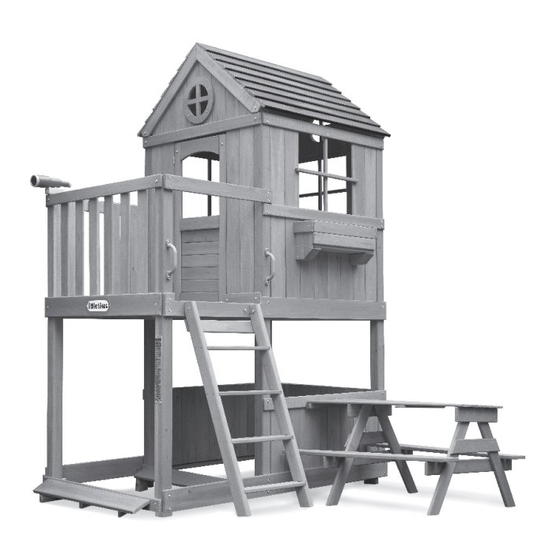
Step 162:
Congratulations, this completes the assembly of the Two Story House.
96
2 Story House
OWNER'S MANUAL &
ASSEMBLY INSTRUCTIONS
ITEM: 657931C3 Little Tikes® • 2180 Barlow Road, Hudson, Ohio 44236 • 1-800-321-0183
THIS PRODUCT IS INTENDED FOR USE BY CHILDREN FROM AGES 3 TO 10.
CAPACITY: 4 USERS MAXIMUM - WEIGHT LIMIT: 110 lbs. (50 kg) PER CHILD
FOR OUTDOOR USE.
For the latest instruction manual, to register your product, or to order replacement parts, please visit:
www.littletikes.com
Please keep this manual as it contains important information.
© The Little Tikes Company, an MGA Entertainment
company.
LITTLE TIKES® is a trademark of Little Tikes in the U.S.
and other countries. All logos, names, characters,
likenesses, images, slogans, and packaging
appearance are the property of Little Tikes.
Printed in U.S.A. · 0821-0-C3
1
At minimum, two people are required
to lift the boxes that contain the parts
for this unit and to assemble this unit.
Little Tikes Consumer Service
2180 Barlow Road
Hudson, Ohio 44236 U.S.A.
1-800-321-0183
Advertisement

Related Manuals for Little Tikes Real Wood Adventures 657931C3


Summary of Contents for Little Tikes Real Wood Adventures 657931C3
- Page 1 OWNER’S MANUAL & ASSEMBLY INSTRUCTIONS ITEM: 657931C3 Little Tikes® • 2180 Barlow Road, Hudson, Ohio 44236 • 1-800-321-0183 THIS PRODUCT IS INTENDED FOR USE BY CHILDREN FROM AGES 3 TO 10. CAPACITY: 4 USERS MAXIMUM - WEIGHT LIMIT: 110 lbs. (50 kg) PER CHILD FOR OUTDOOR USE.
- Page 2 • If you cannot nd a part, check the packing materials thoroughly, as loose parts and small pieces may have shifted in transit. • If any part is missing or damaged, contact Little Tikes Consumer Service: www.littletikes.com or 1-800-321-0183. Please retain these instructions for future reference, and take a moment to write down this information for e cient service.
-
Page 3: Important Safety Information
IMPORTANT SAFETY INFORMATION Step 158: Hammer (1) Ground Anchor (HD23) into the ground next to each Tower Leg (003) as WARNING: INSTRUCTIONS FOR SAFE USE shown. Secure each Ground Anchor using (1) Ground Anchor Screw. • To reduce the risk of serious injury or death, you MUST read and WARNING: follow these instructions before assembly and before use. -
Page 4: Unit Positioning
IMPORTANT SAFETY INFORMATION Step 156: RECOMMENDED SURFACING Align and attach (1) Ground Connect Board (012) to the (3) Brace Boards using (6) WARNING: Screws (S92). To reduce the likelihood of serious head injuries, install shock-absorbing protective surfacing under and around this unit. The protective surfacing should be applied to a depth suitable for the unit height in accordance with ASTM F1292. - Page 5 IMPORTANT SAFETY INFORMATION Step 154: CRITICAL FALL HEIGHT Align and attach (1) Ground Connect Board (024) to the (4) Brace Boards using (8) Maximum critical fall height is 6 feet (2m). The obstacle-free safety zone which requires safety surfacing is a perimeter that extends 6 Screws (S92).
- Page 6 Step 152: INFORMATION ON PLAYGROUND SURFACING MATERIALS Attach (7) Brace Boards (025) to the Baseboard (023) using (14) Screws (S92) as shown. The following information is from the United States Consumer Product Safety Commission’s Information Sheet for playground surfacing material. Additional Information can be found here: https://www.cpsc.gov/s3fs-public/324.pdf SECTION 4 OF THE CONSUMER PRODUCT SAFETY COMMISSION’S OUTDOOR HOME PLAYGROUND SAFETY HANDBOOK Select Protective Surfacing...
- Page 7 Should you elect to use a third party person or service to assemble this product, the manufacturer assumes no responsibility or liability for any charge incurred for any assembly services. Please see our warranty for more information about damaged and missing part replacement coverage. Little Tikes will not reimburse the customer for the price of parts purchased. WOOD WEATHERING Although the manufacturer has taken great care in selecting premium lumber, wood is a product of nature and is susceptible to weathering.
-
Page 8: Limited Warranty
Secure the Picnic Table to the Rail Board (030) using (4) Screws (S96). The Little Tikes Company makes fun, high quality toys. We warrant to the original purchaser that this product is free of defects in materials or workmanship for one year from the date of purchase (dated sales receipt is required for proof of purchase). In addition, all wood carries a pro-rated 5 year warranty against rot and decay. - Page 9 TOOLS Step 146: TOOLS YOU WILL NEED (NOT INCLUDED) INCLUDED TOOLS Align and attach (1) Bench Top Assembly to the Table Supports using (8) Screws (S92). To complete this procedure, you will need a Power Drill, a #2 Double Square Bit (MSC01), Torx Bit Phillips Bit, a Hammer, a Rubber Mallet, a Metric Socket (MSC02), and Allen Wrench (MSC03) Wrench Set, a Level, a Square, an Adjustable Wrench, a Tape...
-
Page 10: Parts List
PARTS LIST Step 144: With the help of another adult, carefully lift the Picnic Table Assembly o the Fort Assembly. Attach the Table Leg (049) Assembly to the Tabletop using (5) Screws (S91). Ensure that the Table Support (050) is facing the Fort Assembly. (1) Baseboard - 320004 (2) Bench Rib - 320053 (2) Baseboard - 320023... - Page 11 Step 142: PARTS LIST CONTINUED Attach (1) Table Rib (052) to the Tabletop Assembly using (5) Screws (S91). Ensure that the Table Rib is attached using the predrilled holes further from the previously installed Table Rib Support. Do not use the closest predrilled holes. (1) Door Support Board - 320060 (1) Floor Rail - 320005 (2) Floor Rail Support - 320016...
- Page 12 Step 140: PARTS LIST CONTINUED Using the predrilled holes, align and center (1) Table Support (050) to the Table Legs. Attach the Table Support to the Table Legs using (8) Screws (S92). (2) Ground Connect Board - 320012 (2) Handle - AC17 (4) Ladder Rung - 320026 (2) Ground Connect Board - 320024 (2) Rail Board - 320021...
- Page 13 PARTS LIST CONTINUED Step 138: Lay out (2) Table Legs (072) as shown. Attach (1) Table Support (045) to the Table Legs using (4) Screws (S91). Ensure that the edges of the Table Support are ush with the outside edges of the Table Legs. (2) Rail Board - 320056 (2) Roof Board - 320036 (1) Rear Support - 320029...
- Page 14 PARTS LIST CONTINUED Step 136: Using the predrilled holes, align and center (1) Table Support (050) to the Table Legs. Attach the Table Support to the Table Legs using (8) Screws (S92). (2) Tower Leg - 320001 (2) Tower Leg - 320002 (2) Tower Leg - 320003 (2) Table Support - 320050 Step 137:...
- Page 15 Step 134: PARTS LIST CONTINUED Using the predrilled holes, align and center (1) Table Support (046) to the top edges of the Table Legs. Attach the Table Support to the Table Legs using (8) Screws (S92). (9) Wall Board - 320017 (10) Wall Board - 320022 (1) Wall Board - 320061 Step 135:...
- Page 16 PARTS LIST CONTINUED Step 132: Align and attach (1) Window Box Assembly with the predrilled holes on the Wall Boards using (14) Screws (S92). (3) Window Board - 320018 (3) Window Board - 320019 (6) Window Box Board - 320069 (6) Window Box Board - 320062 (6) Window Box Support - 320066 (6) Window Box Front - 320065...
- Page 17 ASSEMBLY INSTRUCTIONS Step 130: With the help of another adult, attach (1) Window Box Assembly to the Wall Boards using (14) Screws (S92). Note: To securely attach the Window Box Assembly, rmly press the Window Box against the Wall Boards. Start with the bottom outside Screws, then move up, and nally secure with the remaining (8) Screws.
- Page 18 Step 6: Step 128: The following steps will guide you through the Fort Assembly. Attach (2) Window Box Fronts (065) to the Front Box Supports using (8) Screws (S91). Complete this step 3 times. Step 129: Align (1) Window Box Assembly with the predrilled holes on the Wall Boards (067). Step 7: Insert (4) Nuts (N02) into Tower Leg (003) with the metal warning plates as shown.
- Page 19 Step 8: Step 126: Insert (5) Nuts (N02) into (1) Tower Leg (002) as shown. Orient the Tower Leg with Attach (2) Window Box Boards (062) to the Box Supports using (16) Screws (S92). the (5) holes facing up for use in a later step. Secure the Window Box Boards using (8) Screws (S96).
- Page 20 Step 10: Step 124: Lay out Tower Legs (001), (002), and (003) as shown. Note the orientation of the Attach (1) Front Box Support (064) to the Box Support using (1) Screw (S96). Ensure Nuts on each Tower Leg. that the top edges of the Front Box Supports are ush against the top edges of the Window Box Supports.
- Page 21 Step 122: Step 12: The following steps will guide you through the Window Box Assembly. Attach (1) Baseboard (057) to Tower Legs (001), (002), and (003) using (3) Bolts (B161). Ensure that the Baseboard is ush with the edges of the Tower Legs. Step 13: Step 123: Insert (2) Nuts (N02) into (1) Floor Rail (005) as shown.
- Page 22 Step 14: Step 120: Attach (1) Floor Rail (005) and (1) Floor Rail Support (016) to Tower Legs (001), Attach (1) Roof Board (036) to the Roof Rail Boards using (4) Screws (S91). (002), and (003) using (3) Bolts (B164). Note the orientation of the previously installed Nuts on the Floor Rail and Floor Rail Support.
- Page 23 Step 16: Step 118: Secure the Floor Rail to the Tower Leg (003) using (2) Screws (S96). Align and attach (1) Roof Board (036) to the Roof Rail Boards using (4) Screws (S91). Step 17: Step 119: Attach (1) Rail Board (030) to Tower Legs (001) and (002) using (2) Bolts (B198) and Align and attach (5) Roof Boards (038) to the Roof Rail Boards using (20) Screws (S91).
- Page 24 Step 18: Step 116: Insert (9) Nuts (N02) into (1) Tower Leg (001) as shown. Orient the Tower Leg with Align (1) Roof Board (038) with the Roof Rail Boards (035) ensuring the top edges the (4) Nuts on the ground for use in a later step. are ush.
- Page 25 Step 20: Step 114: Insert (4) Nuts (N02) into (1) Tower Leg (003) as shown. Orient the Tower Leg with Attach (1) Window Pane (073) to Window Boards (014) using (2) Screws (S91). the (3) holes facing up for use in a later step. Attach (1) Window Pane (074) to the Roof Panel Boards (044) using (2) Screws (S91).
- Page 26 Step 22: Step 112: Attach (1) Baseboard (057) to Tower Legs (003), (002), and (001) using (3) Bolts Attach (1) Roof Support (055) to the Roof Panel Boards (043) using (6) Screws (S91). (B161). Ensure that the Baseboard is ush with the edges of the Tower Legs. Ensure that the top edges are ush with the Roof Rail Boards.
- Page 27 Step 110: Step 24: Align (2) Roof Panel Boards (041) to the top edges of the Wall Boards and attach to Attach (1) Floor Rail (008) and (1) Floor Rail Support (016) to Tower Legs (003), (002), the Rail Board (006) using (4) Screws (S95). Attach the Roof Panel Boards (041) to and (001) using (3) Bolts (B164).
- Page 28 Step 26: Step 108: Attach (1) Rail Board (030) to Tower Legs (002) and (001) using (2) Bolts (B198) Attach (2) Roof Panel Boards (043) to the Roof Rail Boards using (4) Screws (S91). and (2) Screws (S96). Ensure that the Rail Board is attached with the Bolts near Align (2) Roof Panel Boards (075) to the outer edges of the Roof Panel Boards (043) the Floor Rail (008).
- Page 29 Floor Rail is aligned with the Floor Rails (005) and (008). Note: Do not use the Floor Rail (007) with the Little Tikes® Logo attached. It will be Attach (1) Window Pane (073) to Window Boards (014) using (2) Screws (S91).
- Page 30 Step 30: Step 104: Attach (1) Baseboard (004) to the Tower Legs (001) using (2) Bolts (B161) Align (2) Roof Panel Boards (042) to the top edges of the Wall Boards. Attach the and (2) Screws (S119). Roof Panel Boards to the Rail Board (039) using (4) Screws (S95). Attach the Roof Panel Boards to the Roof Rail Boards (035) using (4) Screws (S91).
- Page 31 Step 102: Step 32: Align (2) Roof Panel Boards (044) to the bottom edges of the Roof Panel Boards Attach (1) Baseboard (023) to the Tower Legs (002) using (2) Screws (S119) and (2) (075). Attach the Roof Panel Boards to the Rail Board (039) using (4) Screws (S95). Screws (S96).
- Page 32 Screws (S96). Ensure the predrilled holes are near the bottom edge of the Floor Rail and that the Floor Rail is aligned with the Floor Rails (008) and (005). Note: Ensure that the Little Tikes® logo is facing outward. Step 101: Attach (2) Roof Panel Boards (043) to the Roof Rail Boards using (4) Screws (S91).
- Page 33 Step 98: Step 36: Attach the Door Hinges to the Door Support Board (040) using (6) Hinge Attach (1) Rail Board (009) to Tower Legs (002) and (001) using (2) Bolts (B198) and (2) Screws (HD49). Screws (S96). Ensure the predrilled hole is near the top edge of the Rail Board and that the Rail Board is attached with the Bolts near the bottom edge of the Rail Board.
- Page 34 Step 38: Step 96: Attach (1) Rail Board (009) to Tower Legs (001) and (002) using (2) Bolts (B198) and (2) Attach (1) Door Brace (033) to the Door Connect Board (059) using (5) Screws (S91). Screws (S96). Ensure the predrilled hole is near the top edge of the Rail Board and Ensure that the edges of the Door Brace are ush with the edges of the Door that the Rail Board is attached with the Bolts near the bottom edge of the Rail Board.
- Page 35 Step 94: Step 40: Attach (1) Rail Board (039) to the Tower Legs (001) using (2) Screws (S119). Ensure the Attach (5) Door Connect Boards (058) to the Door Support Board and Door Board predrilled hole is near the bottom edge of the Rail Board and that the Rail Board is using (20) Screws (S91).
- Page 36 Step 42: Step 92: Attach (1) Rail Board (006) to the (2) Tower Legs (003) using (2) Bolts (B198). Attach (1) Door Brace (033) to the Door Support (031) using (7) Screws (S91) on the end of the Door Assembly with a larger space between the Hinges. Ensure that the edges of the Door Brace are ush with the edges of the Door Support.
- Page 37 Step 90: Step 44: Carefully turn the Door Assembly over so the Door Board and Door Support Board Attach (1) Handrail Board (070) to the Tower Legs (003) and (002) using (1) Bolt are on the ground. (B161), (1) Screw (S119), and (2) Screws (S96). 180°...
- Page 38 Step 46: Step 88: Place (1) Floorboard (015) on the Floor Rail Supports (016) and Floor Support (037) in Insert (2) Nuts (N02) into (1) Door Support (031). Complete this step 2 times between the Tower Legs (003). Do not attach until instructed to do so in a later step. for 2 Door Supports.
- Page 39 Step 86: Step 48: Attach (1) Door Support Board (040) to the Wall Board (061) using (5) Screws Place (1) Floorboard (015) on the Floor Rail Supports (016) and Floor Support (037) in (S91). Ensure that the edge of the Door Support Board is ush against the edge between the Tower Legs (002).
- Page 40 Step 50: Step 84: Place (2) Floorboards (013) on the Floor Rail Supports (016) and Floor Support (037). Secure the Brackets (HD52) to the Rail Boards (021) using (2) Washers (W07) Do not attach until instructed to do so in a later step. and (2) Screws (S80).
- Page 41 Step 52: Step 82: Place (1) Floorboard (020) on the Floor Rail Supports (016) and Floor Support (037). Attach (3) Wall Boards (017) to the Rail Board (006) using (6) Screws (S95). Attach Ensure that the predrilled bolt holes lay closer to the previously placed Floorboard the Wall Boards to the Rail Boards (021) using (6) Screws (S91).
- Page 42 Step 54: Step 80: Attach (8) Wall Boards (010) to Rail Board (030) using (16) Screws (S95). Attach the Attach (2) Brackets (HD52) to the Floorboard (020) using (2) Nuts (N21) and (2) Wall Boards to Baseboard (057) using (16) Screws (S91). Ensure that the top edges of Bolts (B193).
- Page 43 Step 56: Step 78: Attach (8) Wall Boards (010) to Rail Board (030) using (16) Screws (S95). Attach the Attach (2) Wall Boards (071) to the Rail Board (009) using (4) Screws (S95). Attach Wall Boards to Baseboard (057) using (16) Screws (S91). Ensure that the top edges of the Wall Boards to the Floor Rail (005) using (4) Screws (S91).
- Page 44 Step 58: Step 76: Insert (1) Nut (N02) into (1) Right Upright (028). Insert (1) Nut (N02) into (1) Attach (2) Wall Boards (067) to the Rail Board (056) using (4) Screws (S95). Attach Left Upright (027). the Wall Boards to the Floor Rail (005) using (4) Screws (S91). Ensure that the Wall Boards are ush against the previously installed Wall Boards and that the predrilled holes are near the inner edges.
- Page 45 Step 74: Step 60: Attach (1) Window Board (019) to Wall Boards (067) using (2) Screws (S91). Attach Align the Left and Right Uprights. Note the location of the angled edges. Insert (4) (1) Window Board (018) to Rail Boards (056) and (009) using (2) Screws (S91). Ladder Rungs (026) into the grooves of the Left and Right Uprights.
- Page 46 Step 62: Step 72: Carefully turn the Ladder over so the Rear Support is on the ground. Attach (2) Wall Boards (068) to the Rail Board (009) using (4) Screws (S95). Attach the Wall Boards to the Floor Rail (008) using (4) Screws (S91). Ensure that the Wall Boards are ush against the previously installed Wall Boards and that the predrilled holes are closer to the previously installed Wall Boards.
- Page 47 Step 64: Step 70: Attach the Ladder to the Floor Rail using (2) Bolts (B159). Attach (2) Wall Boards (017) to the Rail Board (056) using (4) Screws (S95). Attach the Wall Boards to the Floor Rail (008) using (4) Screws (S91). Ensure that the Wall Boards are ush against the Tower Legs.
- Page 48 Step 66: Step 68: Attach (2) Wall Boards (067) to the Rail Board (039) using (4) Screws (S95). Attach Attach (2) Wall Boards (071) to the Rail Board (039) using (4) Screws (S95). Attach the Wall Boards to the Floor Rail (007) using (4) Screws (S91). Ensure that the Wall the Wall Boards to the Floor Rail (007) using (4) Screws (S91).
Need help?
Do you have a question about the Real Wood Adventures 657931C3 and is the answer not in the manual?
Questions and answers