Endress+Hauser Micropilot S FMR540 Brief Operating Instructions
Level-radar
Hide thumbs
Also See for Micropilot S FMR540:
- Operating instructions manual (80 pages) ,
- Brief operating instructions (44 pages) ,
- Technical information (36 pages)
Table of Contents
Advertisement
Quick Links
Brief Operating Instructions
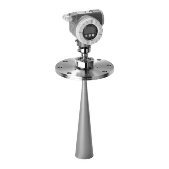
Micropilot S FMR540
Level-Radar
These are Brief Operating Instructions.
For more detailed information, please refer to the Operating Instructions and the
additional documentation on the CD-ROM provided.
These Brief Operating Instructions are not intended to replace the Operating
Instructions provided in the scope of supply.
The complete device documentation consists of:
• these Brief Operating Instructions
• Approvals and safety certificates
• a CD-ROM with:
– the Operating Instructions
– Technical Information
KA01059F/00/EN/12.09
71107706
Advertisement
Table of Contents

Related Manuals for Endress+Hauser Micropilot S FMR540


Summary of Contents for Endress+Hauser Micropilot S FMR540
- Page 1 Brief Operating Instructions Micropilot S FMR540 Level-Radar These are Brief Operating Instructions. For more detailed information, please refer to the Operating Instructions and the additional documentation on the CD-ROM provided. These Brief Operating Instructions are not intended to replace the Operating Instructions provided in the scope of supply.
-
Page 2: Table Of Contents
Table of contents Micropilot S FMR540 4 to 20 mA HART Table of contents 1 Safety instructions ..........3 1.1 Designated use . -
Page 3: Safety Instructions
Micropilot S FMR540 4 to 20 mA HART Safety instructions Safety instructions Designated use The Micropilot S is a compact radar level transmitter for the continuous, contactless measurement of predominantly solids. The device can also be freely mounted outside closed metal vessels because of its operating frequency in the K-band and a maximum radiated pulsed energy of 1 mW (average power output 1μW). -
Page 4: Return
Safety instructions Micropilot S FMR540 4 to 20 mA HART 1.3.1 FCC-approval This device complies with part 15 of the FCC Rules. Operation is subject to the following two conditions: This device may not cause harmful interference, and this device must accept any interference received, including interference that may cause undesired operation. -
Page 5: Installation Instructions
Micropilot S FMR540 4 to 20 mA HART Installation instructions Installation instructions Quick installation guide Marker on sensor neck (Example) Marker on flange ° (Example) L00-FMR54xxx-17-00-00-en-021 Incoming acceptance, transport, storage 2.2.1 Incoming acceptance Check the packing and contents for any signs of damage. Check the shipment, make sure nothing is missing and that the scope of supply matches your order. -
Page 6: Installation Instructions
Installation instructions Micropilot S FMR540 4 to 20 mA HART Installation instructions 2.3.1 Mounting kit For the mounting , you will require the following tool: • The tool for flange mounting • 4 mm (0.1") Allen wrench for turning the housing •... - Page 7 Micropilot S FMR540 4 to 20 mA HART Installation instructions 2.3.3 Orientation • Recommended distance (1) from tank wall to the center of the nozzle: minimum as specified in table on ("Beam angle", → ä 7). • Not in the centre (3), interference can cause signal loss.
- Page 8 Installation instructions Micropilot S FMR540 4 to 20 mA HART Horn antenna Antenna size 100 mm (4") Beam angle (α) 8° Measuring Beamwidth Recommended distance to wall distance (D) diameter (W) 0° tilting 3° tilting 5 m (16 ft) 0,70 m (2.3 ft) 0,89 m (2.9 ft)
- Page 9 Micropilot S FMR540 4 to 20 mA HART Installation instructions 2.3.5 Measuring conditions • The measuring range begins, where the beam hits the tank bottom. Particularly with dish bottoms or conical outlets the level cannot be detected below this point.
- Page 10 Installation instructions Micropilot S FMR540 4 to 20 mA HART Behaviour if measuring range is exceeded The behaviour in case of the measuring range being exceeded can be freely set: The default setting is a current of 22 mA and the generation of a digital warning (E651).
- Page 11 Micropilot S FMR540 4 to 20 mA HART Installation instructions 2.3.7 Standard installation FMR540 with parabolic antenna • Observe installation instructions, → ä 6. • Marker is aligned towards vessel wall. The marker is located clearly visible on the sensor neck or the flange.
- Page 12 Installation instructions Micropilot S FMR540 4 to 20 mA HART 2.3.8 FMR540 with alignment device Micropilot S should be installed vertically towards the Liquid surface for best measuring performance of ± 1 mm. Using the alignment device it is possible to tilt the antenna axis by up to 15°...
- Page 13 Micropilot S FMR540 4 to 20 mA HART Installation instructions 2.3.9 Sensor alignment tool for alignment device A sensor alignment tool (a) is recommended to be used at the time of installation for FMR540 with alignment device. Alignment procedure Note! This procedure is only applicable to the sensors purchased with alignment device (b).
- Page 14 Installation instructions Micropilot S FMR540 4 to 20 mA HART Micropilot S FMR540 with Horn Antenna: Tilt the FMR540 targeting the direction of tank center up to the position where the angle indicators outer circle reaches the circle of 3° (e).
- Page 15 Micropilot S FMR540 4 to 20 mA HART Installation instructions 2.3.10 Sealing for custody transfer applications The alignment device can be sealed using the provided slotted capstan screws. The seal wires must be installed against the open direction in order to assure that a loosening of the alignment device is not possible.
-
Page 16: Post-Installation Check
Installation instructions Micropilot S FMR540 4 to 20 mA HART Post-installation check After the measuring device has been installed, perform the following checks: • Is the measuring device damaged (visual check)? • Does the measuring device correspond to the measuring point specifications such as process temperature/pressure, ambient temperature, measuring range, etc.? -
Page 17: Wiring
Micropilot S FMR540 4 to 20 mA HART Wiring Wiring Warning! When using the measuring device in hazardous areas, installation must comply with the corresponding national standards and regulations and the Safety Instructions (XA00338F) or Installation or Control Drawings (ZD00196F, XA00554F). -
Page 18: Terminal Assignment
Wiring Micropilot S FMR540 4 to 20 mA HART Terminal assignment power: signal: 24 V DC (16…30 V); 24 V DC from a transmitter from a transmitter supply unit supply unit plant ground L00-FMP4xxxx-04-00-00-en-006 Wiring with Tank Side Monitor NRF590 Tank Side Monitor NRF 590 i.s. -
Page 19: Connecting The Measuring Unit
Micropilot S FMR540 4 to 20 mA HART Wiring Connecting the measuring unit Load HART Minimum load for HART communication: 250 Ω Cable entry • Cable gland: M20x1.5 • Cable entry: G½, ½NPT or M20 (thread) Supply voltage DC voltage: 16 to 36 V DC... -
Page 20: Screening/Potential Matching
– The cable shall be protected e.g. routed in an armoured hose. Power supply • For stand alone operation recommended via two Endress+Hauser RN221N. • Integration in tank gauging systems via Tank Side Monitor NRF590 (recommended operation mode), → ä 18. -
Page 21: Operation
Micropilot S FMR540 4 to 20 mA HART Operation Operation General structure of the operating menu The operating menu is made up of two levels: • Function groups (00, 01, 03, …, 0C, 0D): The individual operating options of the device are split up roughly into different function groups. -
Page 22: Display And Operating Elements
Operation Micropilot S FMR540 4 to 20 mA HART The third digit numbers the individual functions within the function group: → • basic setup • tank shape • medium properties • process cond. Here after the position is always given in brackets (e.g. "tank shape" (002)) after the described function. - Page 23 Micropilot S FMR540 4 to 20 mA HART Operation 4.2.1 Display Headline Position indicator ENDRESS + HAUSER Symbol Main value Bargraph Unit – Selection list Help text +21dB Envelope curve 0.00 2.305m 10.00 L00-FMRxxxxx-07-00-00-en-003 4.2.2 Display symbols The following table describes the symbols that appear on the liquid crystal display:...
- Page 24 Operation Micropilot S FMR540 4 to 20 mA HART 4.2.3 Light emitting diods (LEDs) There is a green and a red LED besides the liquid crystal display. LED (LED) Meaning red LED continuously on Alarm red LED flashes Warning red LED off...
-
Page 25: Commissioning
Micropilot S FMR540 4 to 20 mA HART Commissioning Commissioning Function check Make sure that all final checks have been completed before you start up your measuring point: • Checklist "Post-installation check", → ä 16. • Checklist "Post-connection check", → ä 20. -
Page 26: Overview Basic Setup
Commissioning Micropilot S FMR540 4 to 20 mA HART Overview Basic Setup flange: reference point of measurement E = empty calibr. (= zero), setting in 005 F = full calibr. (= span), setting in 006 D = distance (distance flange / product), display in 0A5... - Page 27 Micropilot S FMR540 4 to 20 mA HART Commissioning " Caution! The basic setup is sufficient for successful commissioning in most applications. Complex measuring operations necessitate additional functions that the user can use to customise the Micropilot as necessary to suit his specific requirements. The functions available to do this are described in detail in the BA00341F/00/EN.
- Page 28 Commissioning Micropilot S FMR540 4 to 20 mA HART 5.3.1 Basic setup process tank shape medium property process cond. empty calibr. full calibr. pipe diameter dist. / meas. value start mapping Distance incorrect According to range of mapping check distance...
-
Page 29: Basic Setup With The Device Display
Micropilot S FMR540 4 to 20 mA HART Commissioning Basic Setup with the device display 5.4.1 Function "measured value" (000) ⇒ ENDRESS + HAUSER – This function displays the current measured value in the selected unit (see "customer unit" (042) function). The number of digits after decimal point can be selected in the "no.of decimals"... - Page 30 Commissioning Micropilot S FMR540 4 to 20 mA HART dome ceiling horizontal cyl flat ceiling sphere L00-FMR54xxx-14-00-00-en-002 5.4.4 Function "medium property." (003), liquids only ⇒ ENDRESS + HAUSER – This function is used to select the dielectric constant. Selection: • unknown •...
- Page 31 Micropilot S FMR540 4 to 20 mA HART Commissioning 5.4.5 Function "process cond." (004), liquids only ⇒ ENDRESS + HAUSER – This function is used to select the process conditions. Selection: • standard • calm surface • turb. surface • agitator •...
- Page 32 Commissioning Micropilot S FMR540 4 to 20 mA HART 5.4.6 Function "empty calibr." (005) ⇒ ENDRESS + HAUSER – This function is used to enter the distance from the flange (reference point of the measurement) to the minimum level (= zero) (→ ä 26).
- Page 33 Micropilot S FMR540 4 to 20 mA HART Commissioning 5.4.8 Function "pipe diameter" (007) ⇒ ENDRESS + HAUSER – This function is used to enter the pipe diameter of the stilling well or bypass pipe. Microwaves propagate slower in pipes than in free space. This effect depends on the inside diameter of the pipe and is automatically taken into account by the Micropilot.
- Page 34 Commissioning Micropilot S FMR540 4 to 20 mA HART L00-FMR2xxxx-14-00-06-en-010 distance = ok • mapping is carried out up to the currently measured echo • The range to be suppressed is suggested in the "range of mapping" (052) function Note! Anyway, it is wise to carry out a mapping even in this case.
- Page 35 Micropilot S FMR540 4 to 20 mA HART Commissioning 5.4.11 Function "range of mapping" (052) ⇒ ENDRESS + HAUSER – This function displays the suggested range of mapping. The reference point is always the reference point of the measurement (→ ä 26). This value can be edited by the operator.
- Page 36 Commissioning Micropilot S FMR540 4 to 20 mA HART 5.4.14 Function "set value" (009) ⇒ ENDRESS + HAUSER – This function enables the user to offset the difference between the reference level and the measured level (or between ullage value and measured distance). To make an offset effective, input the reference level measured by the dip measurement by using key buttons.
-
Page 37: Envelope Curve With The Device Display
Micropilot S FMR540 4 to 20 mA HART Commissioning Envelope curve with the device display After the basic setup, an evaluation of the measurement with the aid of the envelope curve (function group "display" (09)) is recommended. 5.5.1 Function "plot settings" (0E1) ⇒... - Page 38 Commissioning Micropilot S FMR540 4 to 20 mA HART 5.5.3 Function "envelope curve display"" (0E3) The envelope curve is displayed in this function. You can use it to obtain the following information: quality of evaluated echo full calibr. evaluated echo is marked empty calibr.
- Page 39 Micropilot S FMR540 4 to 20 mA HART Commissioning Endress+Hauser...
- Page 40 www.endress.com/worldwide KA01059F/00/EN/12.09 71107706 CCS/FM+SGML 6.0 71107706...
Need help?
Do you have a question about the Micropilot S FMR540 and is the answer not in the manual?
Questions and answers